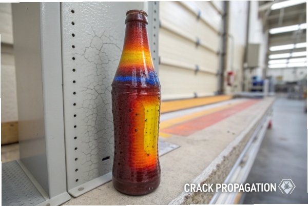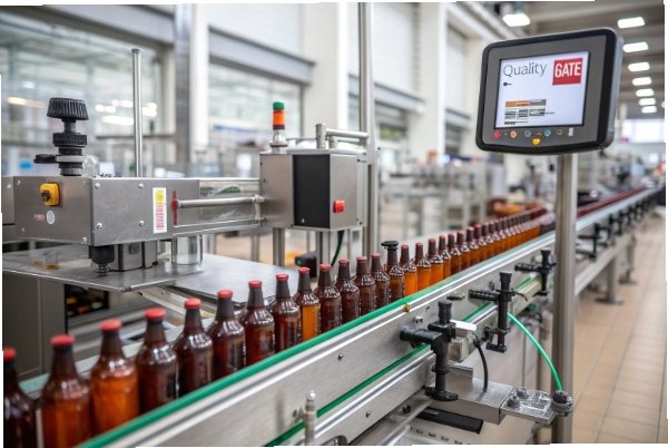
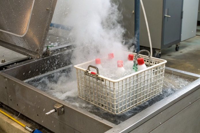
Hot filling looks simple until bottles crack at the line. One cold rinse or one fast stop can turn a stable run into scrap.
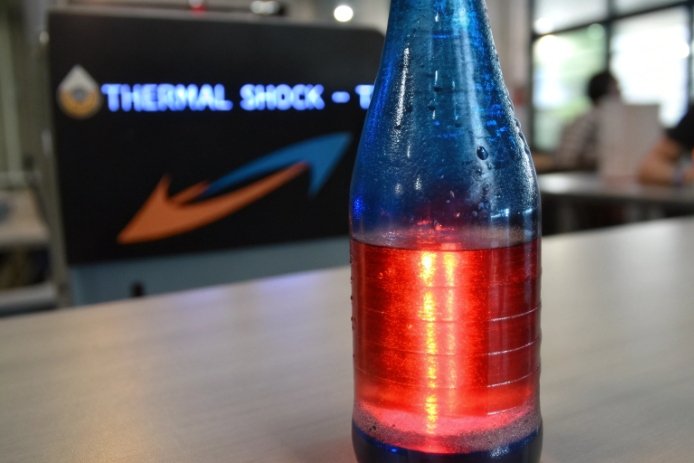
There is no single “maximum ΔT” for all glass bottles. In practice, many soda-lime bottles validate around ΔT 42–50°C in standard container thermal-shock testing, while borosilicate often supports ≥120°C in reference tests. Your real limit depends on wall thickness, design transitions, annealing stress, surface damage, and your heating/cooling steps.

What “maximum ΔT” really means on a hot-fill line?
Two different ΔT values get mixed up
When people say “temperature differential,” they often mean two different things:
-
Fill ΔT (process jump): the difference between product temperature and bottle temperature at fill.
-
Thermal-shock ΔT (wall gradient): the difference that creates stress across the glass wall, often made worse by a cold exterior rinse or cold conveyor contact.
Fill ΔT is easy to calculate. Thermal shock 1 ΔT is what actually breaks bottles, because it is tied to temperature gradients through thickness and stress concentration at the heel, shoulder, and finish.
A simple estimate helps, but it is not the full story
A quick first check is:
- Fill ΔT = T_fill − T_bottle_start
Example: filling at 90°C into a 25°C bottle gives ΔT = 65°C. That can work on some designs, but it becomes risky if the outside is chilled fast, or if the base is thick.
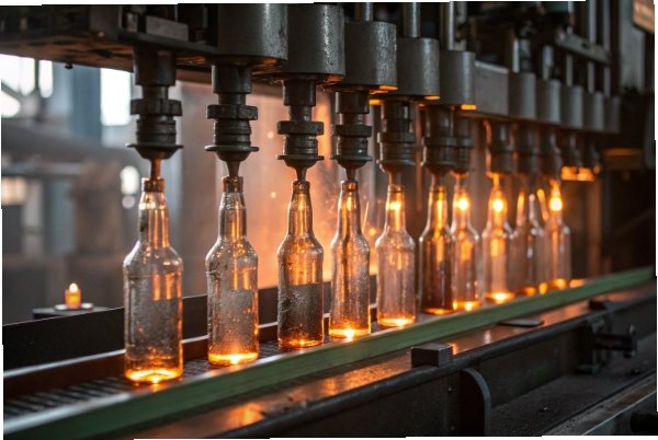
The more dangerous situation is when the inside is hot and the outside is forced cold fast. That is why a “hot-fill bottle” can still crack if it sees a cold rinse, cold air blast, or cold starwheel contact too soon.
Why the base and heel control the real limit
Thick glass heats slowly. So the inner surface expands first while the outer surface still resists. That creates tension, and tension is where glass fails. A premium thick-bottom bottle can crack sooner than a lighter bottle with uniform walls, even if both have the same glass recipe.
| ΔT term | What it means | What drives it in hot-fill | Where cracks start first |
|---|---|---|---|
| Fill ΔT | product vs bottle temperature | product setpoint and pre-warm | heel, shoulder (if big jump) |
| Wall-gradient ΔT | inside vs outside wall | cold rinse, contact cooling | heel/base corner, finish |
| Local ΔT | one zone vs nearby zone | uneven thickness, uneven airflow | one-side cracks, cavity bias |
A useful rule on a real line is to stop thinking in a single “max ΔT” number. Instead, set a safe operating window for bottle start temperature, fill temperature, and cooling steps. Then validate it with a thermal shock test and a line simulation trial.
The sections below show what controls that window, what typical numbers look like for soda-lime vs borosilicate, which standards to use, and which process controls usually give the fastest crack reduction.
What factors determine the maximum hot-fill temperature shock limit (glass type, wall thickness, bottle design, and annealing quality)?
Hot-fill cracking usually comes from a stack of small weaknesses, not one big mistake. When two weaknesses line up, the bottle breaks.
The maximum hot-fill shock limit is set by glass family (CTE and strength), wall thickness and thickness variation (thermal gradients), design transitions (stress concentration), annealing quality (residual stress), and surface damage from handling and conveying.

Glass family sets the baseline stress per degree
Lower CTE materials create less thermal strain for the same temperature gradient. That gives more margin. Still, the glass family is only the baseline. A low-CTE bottle can still fail if the design is sharp or the bottle leaves the lehr with high residual stress.
Thickness and uniformity decide the gradient size
Uniform walls heat and cool more evenly. Thick and uneven sections create “hot core, cold skin” conditions. The heel and base corner are the most common weak points because they combine thick mass and sharp geometry transitions.
Design transitions decide where stress concentrates
Even with perfect thickness control, geometry can amplify stress:
-
sharp heel radii
-
abrupt push-up transitions
-
thick finish rings and narrow sealing lands
-
deep embossing that creates local thickness peaks
A smoother radius often reduces cracking more than adding weight.
Annealing quality decides how much stress is already stored
Residual stress 2 acts like a pre-load. If the bottle is under-annealed or cooled unevenly, thermal stress from hot-fill adds on top. That is how cracking happens even when the recipe-based CTE is “correct.”
Surface condition decides how easily cracks start
Hot-end and cold-end handling damage matters. Small scratches at the heel or finish can turn a safe ΔT into a failure ΔT. This is why line simulation pre-treatments are useful during validation.
| Factor | How it lowers the real ΔT limit | What to control first | Fast sign it is the culprit |
|---|---|---|---|
| High CTE glass family | higher stress per °C | confirm glass family and CTE band | cracks increase with higher fill temp |
| Thick base / uneven walls | higher gradients | reduce thickness steps, improve distribution | heel cracks, cavity differences |
| Sharp transitions | stress concentration | increase radii, smooth push-up | cracks at same geometry point |
| Poor annealing | residual stress | lehr profile 3 and airflow balance | polariscope shows high stress patterns |
| Surface damage | crack starters | coatings, lubrication, conveyance | cracks after conveyance changes |
When the target is “maximum allowable ΔT,” the best path is to fix the largest gradient and stress drivers first. Many lines gain a lot of margin without changing glass type, just by improving thickness uniformity, annealing, and cooling control.
What temperature differential is typically achievable for soda-lime glass bottles versus borosilicate bottles in hot-fill lines?
People often want a single number. The most honest answer is a range, tied to a test method.
For many commercial soda-lime containers, typical pass levels in container thermal-shock QC tests are around ΔT 42°C for beverage and about ΔT 50°C for hot-fill products. Borosilicate 3.3 reference data often recommends not exceeding about 120°C, with thicker sections limiting the usable ΔT.
Soda-lime bottles: common hot-fill validation windows
Soda-lime glass 4 is the standard for beverage and many food bottles. Many plants treat thermal shock resistance as a pass/fail QC test, not a design rating. In that style of testing, typical pass levels used in industry presentations are around:
-
~42°C for beer/beverage
-
~50°C for hot-fill products
These values are not a promise that every soda-lime bottle will survive any 50°C event. They are practical targets that many lines use for screening and comparison.
In real hot-fill production, the line may see higher fill ΔT (product vs bottle start temperature), but the bottle survives because the outside is not chilled too fast and because the bottle design is forgiving. When the outside is chilled fast, cracks show quickly.
Borosilicate bottles: much higher margin, but still not unlimited
Borosilicate 3.3 5 has much lower CTE, and it is built for thermal shock. Reference property pages define thermal shock resistance as a ΔT at which a portion of samples crack under a quench test, and they recommend not exceeding about 120°C in general guidance. That guidance also says the safe ΔT drops as wall thickness rises. That matches real container experience: thick zones reduce the practical margin.
So borosilicate often supports a much wider thermal window for sterilization-like conditions. The trade is cost, forming practice, and supply availability.
| Glass type | Common practical ΔT targets used in container testing | What it usually supports on hot-fill lines | What most often limits it |
|---|---|---|---|
| Soda-lime container glass | ~42–50°C | many hot-fill programs with good controls | thickness gradients + residual stress |
| Borosilicate 3.3 | ~120°C guidance (often higher in thin sections) | harsh thermal cycles and wider ramps | thickness, surface condition, cost |
A clean way to set expectations with customers is to state the test method used, then state the validated safe operating window for bottle start temperature, fill temperature, and cooling steps.
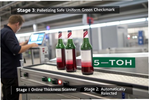
Which thermal shock tests and standards should you use to validate the maximum allowable ΔT before mass production?
A “max ΔT” statement is only meaningful if the test is defined. Without that, two suppliers can both claim success and still ship different risk.
Use container-focused thermal shock standards like ASTM C149 and the ISO/DIN 7459 method for commercial glass containers, then add a line-simulation hot-fill trial that matches your exact fill temperature and cooling steps. Pair those tests with annealing stress inspection so results are repeatable batch to batch.
Standard QC tests for commercial containers
Container thermal shock standards are designed to rank and screen bottles. They typically use controlled hot/cold conditions and require inspection for cracks after each step. This is useful for:
-
comparing designs
-
qualifying a new mold set
-
setting internal QC pass/fail levels
Line simulation trials are the real proof for hot-fill
Hot-fill cracking depends on timing:
-
when product hits the bore and finish
-
when exterior cooling starts
-
when bottles touch cold metal
-
how long the hot zone stays hot
So validation should also include a pilot run or lab simulation that reproduces:
-
bottle starting temperature
-
fill temperature and hold time
-
rinse temperature and timing
-
stop/start scenarios
Stress inspection makes results stable
A thermal shock test can fail because of residual stress, not because the bottle “cannot take ΔT.” A polariscope check by cavity helps separate process drift from design limits.
| Validation tool | What it proves | Best use time | What to record for traceability |
|---|---|---|---|
| ASTM C149 6 / ISO 7459 7 thermal shock | comparative resistance of containers | design release and QC | cavity ID, crack origin, ΔT step |
| Hot-fill line simulation | true process survival | before mass rollout | fill temp, rinse timing, stop/start |
| Polariscope stress inspection | annealing quality and uniformity | every batch/shift | stress pattern by cavity |
| Thickness/weight mapping | gradient risk hot spots | daily or per change | heel/base thickness distribution |
| Leak/closure tests at heat | seal integrity under cycling | product qualification | torque, back-off torque, leak rate |
If the goal is “maximum allowable ΔT,” the best standard-plus-process approach is: use ASTM C149 or ISO/DIN 7459 for baseline screening, then validate with your real hot-fill profile. That is the fastest path to a number you can defend in production and in customer audits.
How can you reduce hot-fill cracking risk by process controls (pre-warming bottles, controlled cooling, fill temperature windows, and closure timing)?
Many cracks are process-created. That is good news, because process controls are often faster than changing glass type.
Reduce hot-fill cracking by reducing the gradient: pre-warm bottles, keep fill temperatures inside a stable window, delay or soften exterior cooling, and apply closures at a controlled neck temperature so the finish does not see stacked thermal and mechanical stress.
Pre-warm bottles to shrink fill ΔT
Pre-warming does not need to be extreme. Even a moderate rise in bottle start temperature reduces the sudden jump at fill. This also makes the finish temperature more consistent for capping.
Control cooling so the outside does not get shocked
The biggest trap is fast cooling on the outside while the inside is still hot:
-
cold rinses too early
-
cold air blasts on the base
-
cold starwheel contact on thick heels
A staged cooling profile usually reduces cracking more than lowering fill temperature by a few degrees.
Hold fill temperature in a tight window
Wide swings in fill temperature create wide swings in stress. A stable fill window makes bottle performance predictable. It also helps closure and liner performance, because liners soften and creep more at higher temperatures.
Time closure application to the finish temperature
Capping while the finish is too hot can reduce torque retention and liner compression. Capping while it is too cold can create high application stress and sometimes finish damage. The best practice is to cap in a controlled temperature band, then verify with torque and leak tests after heat soak and after cool-down.
| Process control | What it reduces | Simple implementation | What to watch on the line |
|---|---|---|---|
| Bottle pre-warm | fill ΔT | warm air tunnel or controlled staging | crack rate vs bottle start temp |
| Staged cooling | outside shock | delay cold rinse, use warmer first rinse | heel crack timing after fill |
| Fill temp window | stress variability | tighter heater control and alarms | ΔT trend chart per hour |
| Stop/start plan | worst-case shocks | defined restart protocol | crack spikes after stops |
| Closure timing band | stacked stress at finish | cap at controlled neck temp | torque retention after heat |
A stable hot-fill program usually comes from controlling the first 60 seconds after fill. That is when gradients are largest, liners are softest, and pressure is highest. When those minutes are controlled, “maximum ΔT” becomes less important because the bottle is no longer being shocked.
Conclusion
Maximum hot-fill ΔT is not one fixed number. Use standards to set a baseline, then validate your real process window with thickness, annealing, and cooling controls so bottles survive at scale.
Footnotes
-
The ability of glass to withstand rapid temperature changes without breaking. ↩
-
Internal tension remaining in glass after improper cooling. ↩
-
The critical cooling process to prevent glass breakage. ↩
-
The most common glass type for food and beverage containers. ↩
-
High-performance glass with low thermal expansion properties. ↩
-
Standard test method for thermal shock resistance of glass containers. ↩
-
International standard for thermal shock resistance and endurance. ↩