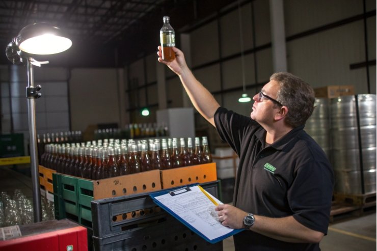
Scrap can jump overnight. Bottles look fine at the lehr exit, then show scuffs, checks, and breaks downstream. The real causes hide in friction, stress, and tiny flaws.
Scratches and cracks usually come from three linked drivers: high friction contact, weak glass zones (thin walls or inclusions), and harmful stress from forming or cooling. Good coatings, stable handling, and tight QA cut damage fast.

The real root cause chain behind most damage
Scratches are not cosmetic, they are strength killers
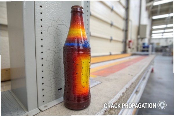
A scratch is a crack starter. Glass fails from the surface, and glass failure originates from flaws at the surface 1. A micro-scratch can cut strength far more than people expect. When a bottle later sees impact, capping load, or thermal swing, the crack grows fast. So a “small scuff” on a conveyor can become a “random break” at the filler.
Cracks usually need two things: a starter and a stress
A crack starter can be a scratch, a sharp mold seam, an inclusion, or a check from thermal shock. Stress can be residual stress from poor annealing, tensile stress from handling, or local stress from uneven thickness. When both meet, failure happens—especially when the annealing lehr temperature and cooling curve 2 drift out of control.
Most plants see the same feedback loop
When damage rises, operators often raise speed or cooling to recover output. That can increase friction and stress. Damage rises again. The fastest recovery comes from breaking the loop and fixing the true driver.
| Damage type | Typical first location | Common trigger | Hidden amplifier | Best first measurement |
|---|---|---|---|---|
| Sidewall scuff | transfer points, rails | high line pressure, high COF | weak cold-end coating | COF trend + scuff map by section |
| Base wear | dead plates, starwheels | sliding contact | rough plate surface | base scuff rate + plate inspection |
| Vertical checks | shoulder, heel | molds too cold, drafts | high residual stress | lehr exit stress check + zone cooling audit |
| Ring/finish cracks | finish/threads | high capping torque, misfit | thin finish wall | torque audit + finish gauges |
| Breaks after days | random | micro-scratch + stress | rough handling | break origin tracking |
The goal is not only “less contact.” The goal is controlled contact with a protected surface and a low-stress bottle.
Keep reading, because each next section turns one cause into a fast correction plan.
Do conveyor friction and poor COF drive abrasion checks?
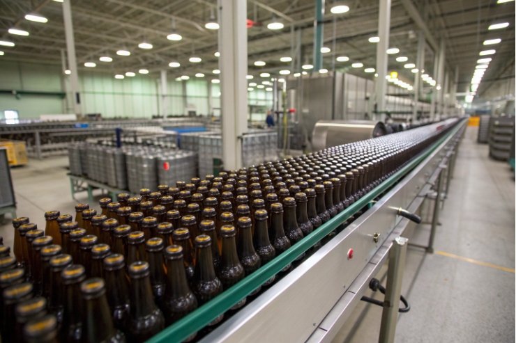
When a line runs fast, bottles touch more often than anyone wants to admit. A small rise in friction can turn gentle contact into grinding.
Yes. High conveyor friction, high line pressure, and unstable COF cause scuffs and abrasion checks. The fix is to lower contact energy, stabilize COF with cold-end control, and remove high-friction transfer points.
How friction turns into scratches
A bottle scratches when it slides under load. The load comes from back pressure, lane merges, dead plates, and starwheels. The sliding comes from speed mismatches and poor transfer design. When COF is high, the same load makes deeper scratches. When COF is uneven, scratch patterns become random and hard to debug.
The most common friction hot spots are:
- dead plates and bridges where bottles slide,
- tight turns with high side pressure,
- accumulation zones where bottles rub,
- worn guide rails and dirty belts,
- starwheel infeed/outfeed timing mismatch.
A second hidden driver is dust. Fine glass dust, label dust, or carton dust can turn a smooth contact into abrasive contact. That is why a line can “get worse” late in the shift.
COF is a coating and cleanliness story
Cold-end coatings exist for a reason. If the coating is thin, patchy, or contaminated, COF rises. If the coating is too heavy or uneven, COF becomes unstable. Both cases increase damage. The fastest control lever is to lock the cold-end spray process and verify coverage, then tune line pressure and transfers—starting with the right cold-end coating materials 3.
A fast correction plan that works in real time
Start where energy is highest, not where the scuff is visible.
1) reduce back pressure and tighten accumulation control,
2) fix dead plates and worn transfer parts,
3) confirm cold-end coating stability and spray patterns,
4) clean dust sources and add targeted air knives where needed.
| Symptom on bottles | Likely friction cause | Fast confirmation | Fast correction |
|---|---|---|---|
| broad matte scuff band | long sliding contact | scuff aligns with one conveyor zone | lower pressure, add rolling transfer, polish plate |
| vertical scuff lines | rail rub | marks match guide rail height | adjust rails, replace worn UHMW, reduce side load |
| base ring wear | dead plate | ring pattern repeats | change plate material/finish, reduce drop height |
| random fine scratches | abrasive dust | rises late shift | clean, improve housekeeping, isolate dust sources |
| “abrasion checks” later | micro-scratch + stress | breaks show scuff origin | reduce scuff and confirm annealing quality |
When COF is stable and contact is controlled, the damage rate drops quickly. That is often the fastest win on a high-speed line.
Can thin walls, inclusions, or stress lead to crack initiation?
A bottle can leave the IS machine looking perfect and still be fragile. The weakness is often hidden in thickness maps, inclusions, or stress patterns.
Yes. Thin-wall zones, inclusions like stones or cords, and harmful residual stress all create crack initiation sites. These issues turn normal handling loads into breaks, even without visible surface damage.
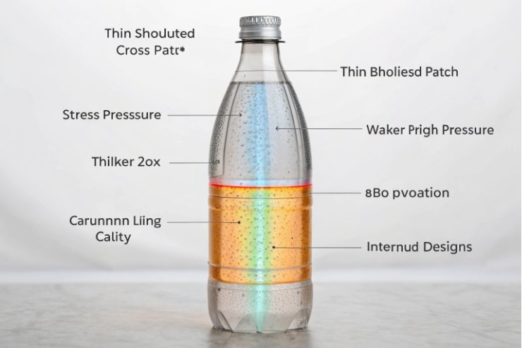
Thin walls create local overload
Thin walls reduce the safety margin. A small impact that a normal wall can absorb becomes a break on a thin shoulder or heel. Lightweight bottles are more sensitive because small process drift changes thickness distribution fast. Thin heels are especially dangerous because the base sees shock loads from conveyors and packers.
The most reliable way to control thin-wall cracking is to control distribution at forming:
- keep gob weight stable,
- keep blank and blow timing stable,
- keep mold temperatures uniform,
- verify thickness by cavity, not only average.
Inclusions act like built-in stress raisers
Stones, cords, seeds, and blisters 4 are not only appearance defects. They change local stiffness and can concentrate stress. A cord line can guide a crack. A stone near the surface can start a fracture under impact. A blister can weaken a region and change stress.
The practical control is to treat inclusion rates as a melt and refining KPI:
- furnace stability and refining time,
- batch quality and cullet cleanliness,
- feeder cleanliness and shear stability,
- inspection to remove outliers before packing.
Stress is the silent partner
Residual stress from poor annealing can turn small flaws into big breaks. Thermal drafts at the lehr entrance, fast cooling, or unstable lehr control can leave stress patterns that later trigger checks or delayed breaks. Stress also interacts with capping and filling loads. A stressed finish is more likely to crack under torque or closure mismatch, which is why routine polariscope inspection 5 matters.
| Crack origin | What it usually means | What to measure first | Best immediate action |
|---|---|---|---|
| heel crack | thin heel or hot bottom plate | heel thickness by cavity | adjust bottom cooling and timing |
| shoulder crack | thin shoulder or over-stretch | shoulder thickness map | tune blank stretch and blow timing |
| random body crack | inclusion or high residual stress | break origin + polariscope spot check | isolate cavities, check lehr and melt quality |
| delayed warehouse breaks | stress + micro-damage | residual stress trend | tighten annealing control and handling |
| finish crack | torque, misfit, or stressed neck ring | torque audit + finish gauge | correct torque window, check neck ring temps |
A strong QA program tracks break origin. That data cuts troubleshooting time. It also prevents repeating the same “random” failures every season.
How do mold wear and swabbing create scuff patterns?
Some scuffs start before the bottle ever touches a conveyor. Mold contact and release can leave patterns that look like handling damage but are actually forming damage.
Worn molds, misaligned neck rings, and inconsistent swabbing can create repeatable scuff patterns and micro-checks. These defects often repeat by cavity and appear at the same height on every bottle.
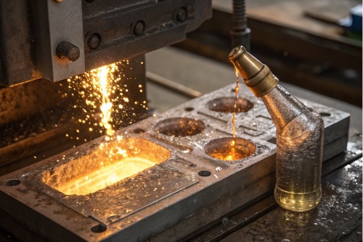
Mold wear creates sharp contact and poor release
Molds wear at edges, vents, seams, and engraving details. When wear creates a burr or a sharp edge, the glass can pick up a line mark. When alignment drifts, the parting line becomes more aggressive. When venting is poor, the glass sticks and pulls, leaving drag marks.
Neck rings and guide parts matter even more. A worn neck ring can damage the finish and create cracks that show up later at the capper. A poor neck ring temperature can also create checks near the shoulder.
Swabbing is both lubrication and thermal control
Swabbing helps release and surface finish, but it also changes heat transfer:
- a heavy film can insulate and create “orange peel” surface,
- an uneven swab can create hot and cold bands,
- a wet swab can chill the surface and raise check risk,
- a missed swab can cause sticking and drag scratches.
When swabbing style varies by operator, defect rates vary by shift. That is why swabbing needs standard work.
How to separate mold scuff from conveyor scuff
The easiest method is pattern logic:
- mold scuff repeats by cavity and stays at a fixed height,
- conveyor scuff often changes with line events and can shift location.
| Pattern | More likely source | Quick confirmation | Fast fix |
|---|---|---|---|
| same scratch height on every bottle | mold seam or vent | defect clusters by cavity | repair mold edge, clean vents, check alignment |
| drag mark near parting line | sticking due to surface or swab | rises after swab change | standardize swab interval and film amount |
| orange peel texture | hot mold or heavy lubricant film | texture follows swab cycle | adjust mold cooling, reduce film, clean mold |
| finish ring checks | neck ring wear or temp | finish crack clusters by cavity | refurb neck ring, control neck ring temperature |
| random scuffs | conveyor contact | shifts with line pressure | reduce back pressure, improve transfers |
A plant that logs defects by cavity and shift can find these causes quickly. Without that data, teams often blame conveyors for a mold issue or blame molds for a conveyor issue.
Which QA and coatings reduce damage rates?
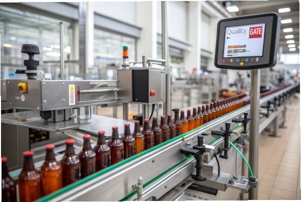
Damage control is not one tool. It is a system: coating coverage, handling design, and inspection discipline that catches drift early.
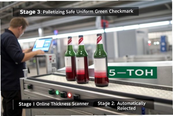
The best damage reduction stack is: stable hot-end protection, stable cold-end lubrication for low COF, inline inspection by cavity, and a QA loop that ties defect trends to fast corrective actions.
Coatings: protect the surface before the first contact
Hot-end coatings improve surface durability right after forming. Cold-end coatings reduce friction and protect against scratches during conveying and packing. When either one is uneven, damage rates rise fast. Coating control should include:
- spray pattern verification,
- coverage checks by section,
- COF trend tracking,
- and periodic calibration of dosing equipment.
For hot-end protection, hot-end tin-oxide coating 6 is a common baseline, and many plants rely on a proven combination of hot-end and cold-end coatings 7 to improve scratch resistance and lubricity.
Handling must match the coating. Even the best coating cannot survive extreme back pressure and rough transfers.
QA: measure the right things at the right time
Damage QA works best when it focuses on leading indicators:
- COF trend and scuff maps,
- wall thickness distribution,
- finish dimensions and torque behavior,
- residual stress checks for annealing stability,
- defect codes split by cavity and by hour.
Break origin analysis should be routine, not only for big events. A simple break origin photo library helps operators classify failures consistently.
A simple “damage reduction checklist” buyers can require
Buyers often ask what to request from a supplier. The request should be measurable and linked to performance.
| Buyer requirement | What it prevents | How to verify | Practical pass signal |
|---|---|---|---|
| hot-end + cold-end coating control plan | early scratches and COF drift | coating process audit + COF records | stable COF band and low scuff rate |
| thickness capability by cavity | thin-wall crack risk | thickness map and Cpk | no cavity outliers beyond limit |
| annealing quality checks | checks and delayed breaks | polariscope sampling | stable stress grade per lot |
| finish gauge + torque window control | finish cracks at capping | torque audit and gauges | torque within window, low leaker rate |
| inline inspection with cavity traceability | repeat defects from one cavity | defect split reports | fast isolation of bad cavity |
| line simulation handling test | scuffs from logistics | vibration and rub tests | no critical scuff at target load |
When QA is structured this way, improvements stick. Damage rates drop, and they stay low even after job changes and seasonal airflow shifts.
Conclusion
Scratches and cracks come from friction, weak zones, and stress acting together. Control COF and transfers, prevent thin-wall and inclusions, standardize swabbing, and prove stability with coating control plus cavity-level QA.
Footnotes
-
Explains why surface flaws dominate glass strength and why tiny scratches can trigger brittle fracture. (↩︎) ↩
-
Practical overview of lehr annealing and why temperature/cooling profiles control residual stress in containers. (↩︎) ↩
-
Technical notes on cold-end coatings, lubricity, and why clean glass surfaces show high friction without protection. (↩︎) ↩
-
Quick visual glossary of common container glass inclusions and sidewall defects used for defect ID and troubleshooting. (↩︎) ↩
-
Shows how polariscopes reveal residual stress patterns that correlate with checks, delayed breaks, and weak zones. (↩︎) ↩
-
Describes hot-end tin-oxide coating chemistry and how it improves surface durability before cold-end coating. (↩︎) ↩
-
Background on dual-end coating systems and how pairing hot-end and cold-end improves scratch resistance and lubricity. (↩︎) ↩