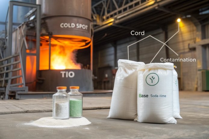
TiO₂ looks harmless as a “minor oxide,” but one cold corner in the forehearth can turn it into stones, haze lines, and higher breakage.
TiO₂ can increase devitrification risk when it rises above normal sand background or when it concentrates locally. The real trigger is not TiO₂ alone, but TiO₂ plus cold spots, poor mixing, and a tight liquidus margin.

TiO₂ is not a devit “switch,” it is a nucleation helper that amplifies weak process zones
TiO₂ is famous in glass-ceramics because it can act as a nucleating agent. That reputation makes bottle teams nervous. The truth is more practical. In a normal soda-lime bottle recipe, devitrification starts when the melt sits below the liquidus temperature 1 long enough for crystals to nucleate and grow. TiO₂ mainly changes how easy it is for that first nucleus to appear, and which crystal wins the race.
In standard container production, TiO₂ enters mostly as an impurity from silica sand and heavy minerals. Many glass-sand specifications keep TiO₂ low because it can affect color and is hard to “neutralize” compared with iron. In some sand guidance, TiO₂ in glass sand is recommended below about 0.03%. That number is not magic, but it is a good “background vs intentional addition” divider for clear flint and high-white work.
When TiO₂ is intentionally pushed higher, it can form its own Ti-bearing crystals (like rutile), and it can also help nucleate common soda-lime devit phases if the furnace gives it time in the danger zone. The phases that show up depend on the rest of the chemistry. Soda-lime devitrification often involves sodium-calcium silicates (several Na–Ca–Si phases are reported in devitrified melts in the 900–1000 °C range). TiO₂ can add rutile nuclei on top of that, and those nuclei can then seed other phases if the local chemistry supports it.
The best way to manage TiO₂ is to treat it like a “risk amplifier.” If the furnace and forehearth are stable, small TiO₂ drift usually does not matter. If there are cold spots, dead zones, or unstable fining, TiO₂ makes the outcome worse and faster.
| TiO₂ situation | What usually happens | Typical defect mode | What decides severity |
|---|---|---|---|
| Background TiO₂ (clean sand) | little change in devit tendency | none or mild striae | liquidus margin and temperature uniformity |
| Moderate TiO₂ rise | easier nucleation in cold zones | surface crystals, haze lines | forehearth corners, residence time |
| Local Ti-rich pockets | Ti-bearing stones form | stones, cords around inclusions | batch mixing, raw material grain size |
| High TiO₂ intentional | rutile + other phases become likely | haze, stones, yield loss | full melting/refining capability |
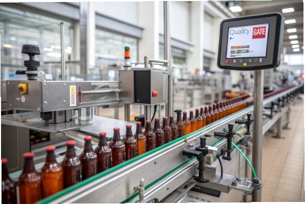
If TiO₂ is being discussed, it usually means the plant already saw haze, stones, or cord lines. So the next step is to define where the TiO₂ “risk curve” rises and which crystals are most likely.
This leads into dosage and phase selection.
At what TiO₂ dosage does nucleation risk rise in soda-lime glass, and which crystal phases are most likely to form?
A bottle can look fine in the lab and still grow crystals on the line, because the line has cold walls, dead zones, and long residence time.
Nucleation risk usually starts to rise when TiO₂ moves from “sand impurity background” into “intentional additive territory,” roughly above a few tenths of a percent in many soda-lime systems, or when local Ti-rich lumps exist. The most common Ti-related phase is rutile, and the most common soda-lime devit phases are Na–Ca silicates that TiO₂ can help seed.
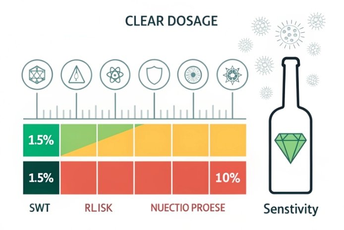
A practical dosage map for bottle plants
For clear flint and high-white work, TiO₂ is often treated like an impurity to minimize. Some guidance for glass sand targets TiO₂ below ~0.03% because it can color glass and is hard to counteract. That “0.03%” level matches what many buyers already do for premium flint: keep TiO₂ very low and stable.
From there, the next bands are more about risk than about strict chemistry:
- ~0.03–0.10 wt% TiO₂: still “impurity band,” but cold spots can start showing more surface crystals if other drivers exist.
- ~0.10–0.30 wt% TiO₂: “sensitive band,” where local pockets and forehearth cold corners matter more.
- ~0.30–1.0 wt% TiO₂: “intentional additive band,” where TiO₂ behaves like a known nucleation helper in many silicate glasses. Some patents and glass-ceramic designs even define “substantially free of nucleating agents” as below about 0.3 mol% of TiO₂/ZrO₂/P₂O₅, which gives a useful mental threshold: beyond that, nucleation behavior is no longer negligible.
The key point is that the local TiO₂ concentration can be far higher than the average if raw materials segregate or if Ti-bearing minerals enter as coarse grains. That local spike is what creates stones.
Most likely crystal phases
In soda-lime devitrified melts, sodium-calcium silicates are commonly reported in the 900–1000 °C range (multiple Na–Ca–Si phases appear in studies of devitrified soda–lime–silica melts). TiO₂ does not need to create a new phase to cause trouble. It can help those phases nucleate sooner at the wall.
When TiO₂ forms its own crystals, rutile (TiO₂) is a frequent one. In a soda-lime silica glass crystallization study with TiO₂ addition, rutile peaks were identified after heat treatment. In simpler SiO₂–TiO₂ glasses, rutile and cristobalite 2 have been reported during devitrification. If CaO is high and the local chemistry supports it, Ti can also enter Ca–Ti silicate phases (titanite/sphene is a common CaO–SiO₂–TiO₂ devit product in related ceramic frit systems), and CaTiO₃ becomes relevant in Ti-rich Ca-bearing systems.
| Phase family | Likely crystal | Where it shows up on a bottle line | Why it matters |
|---|---|---|---|
| Soda-lime devit family | Na–Ca silicates (multiple Na–Ca–Si phases) | forehearth walls, spout area | creates haze lines and flakes |
| Ti-bearing | rutile (TiO₂) | Ti-rich pockets, cold surfaces | hard stones, “sparkle” inclusions |
| Ca–Ti silicate | titanite (CaTiSiO₅) in Ca–Si–Ti systems | Ca-rich, Ti-rich zones | opaque seeds and stones |
| Silica polymorph | cristobalite (SiO₂) in some Ti-containing systems | high SiO₂, long hold | thermal mismatch and checks |
This is why TiO₂ control is never only “keep Ti low.” It is “keep Ti low and uniform, and keep the line above the liquidus margin.”
How do Al₂O₃, CaO/MgO balance, and ZrO₂/Fe₂O₃ levels interact with TiO₂ to promote or suppress devit?
Teams often blame TiO₂ first. In many plants, TiO₂ is only the last piece that made a weak chemistry balance visible.
TiO₂ interacts strongly with the devit drivers that already exist: CaO/MgO pushes which primary silicate crystals form, Al₂O₃ changes liquidus and growth kinetics, ZrO₂ can add extra nucleation power, and Fe redox affects melt oxygen balance and how Ti changes state.
Al₂O₃: usually a stabilizer, sometimes a phase shifter
Al₂O₃ often helps container glass durability and can reduce the tendency for some silica polymorphs to form. Modeling work on soda-lime type systems shows cristobalite formation temperature decreases with additions of other components, and Al₂O₃ is one of the stronger reducers of cristobalite tendency compared with pure high-silica. At the same time, classic devitrification studies show that changing Al₂O₃ vs CaO changes which phase becomes primary at the liquidus. That means Al₂O₃ can suppress one devit route while making another route more competitive, depending on the base recipe.
In practice, Al₂O₃ helps most when it is used to widen the working window and stabilize the melt, not when it is pushed so high that melting and homogenization suffer.
CaO/MgO balance: the biggest “which crystal wins” lever
CaO promotes Ca-silicate devit tendencies in soda-lime systems. MgO also matters. Some published work notes that substituting lime with magnesia can decrease crystal growth rate for key devit phases in soda-lime glasses. So MgO can be a practical “growth rate brake” when devit appears at the wall.
Still, too much MgO can tighten viscosity 3 and change forming. So the goal is not “high MgO.” The goal is “enough MgO to slow growth without shrinking the forming window.”
ZrO₂ and TiO₂ together: nucleation stacking
ZrO₂ and TiO₂ are both common nucleation helpers in glass-ceramic design. If both drift upward, nucleation risk rises faster than expected. Even if each oxide is “small,” the combined nucleation power can be enough to create surface crystallization 4 where a single oxide would not.
Iron mainly controls color and UV behavior, but it also tracks furnace oxygen potential. Batch redox and oxygen partial pressure control the Fe²⁺/Fe³⁺ ratio in container glass practice. Titanium also has a Ti⁴⁺/Ti³⁺ equilibrium in silicate melts. If the furnace runs too reducing, Ti³⁺ can appear and change absorption and local structure. The point is not “Ti causes redox problems.” The point is that unstable furnace redox 5 makes every minor oxide behave less predictably.
| Oxide lever | How it changes TiO₂ devit risk | Practical meaning | Typical control style |
|---|---|---|---|
| Al₂O₃ | can suppress silica polymorph routes; can shift liquidus phase | changes which crystal is favored | small, steady adjustments |
| CaO ↑ | promotes Ca-silicate devit routes | faster wall crystals if cold zones exist | keep within proven window |
| MgO ↑ (vs CaO) | can slow growth of some devit phases | fewer devit flakes at same liquidus | tune CaO/MgO ratio |
| ZrO₂ ↑ | adds extra nucleation sites | devit starts earlier in cold zones | keep Zr stable, avoid spalls |
| Fe redox drift | changes oxygen balance; affects Ti state | cords + color drift + unstable fining | stabilize combustion and batch redox |
When TiO₂-related defects show up, the fastest wins often come from CaO/MgO and temperature uniformity, not from chasing TiO₂ alone.
Now the line needs actions: furnace control, redox control, and cooling discipline.
A chemistry fix that ignores the furnace is slow and expensive. A furnace fix that ignores chemistry is temporary.
To minimize TiO₂-related devit, the melt must stay above the liquidus margin in every weak zone, redox must stay stable to avoid chemistry banding, and cooling must avoid long holds in the crystallization window near walls and spouts.
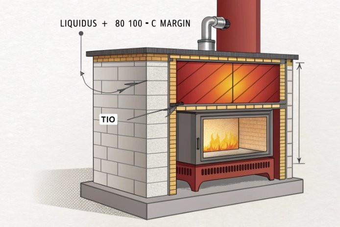
1) Protect the liquidus margin everywhere, not only in the tank
Devitrification is driven by the liquidus rule: above the liquidus, crystals dissolve; below it, crystals can form and grow. Many devit events in bottles are not tank events. They are forehearth and feeder events. So the control plan has to map temperatures at:
- forehearth corners
- throat exits
- feeder bowls and spouts
- any zone with slow flow or stagnant recirculation
If one corner sits below the practical liquidus margin for hours, TiO₂ will make nucleation easier and the wall will grow crystals faster.
2) Stop local Ti-rich pockets before they enter the melt
Most “Ti stones” begin as raw material problems:
- coarse Ti-bearing minerals (rutile/ilmenite) entering with sand or cullet contamination 6
- segregation in the batch house
- poor mixing that creates chemistry bands
The fix is boring but effective: tighten sand and cullet screening, control grain size distribution, and keep batch mixing consistent.
3) Keep redox steady to prevent cords and unstable fining
Container glass practice uses batch redox concepts to control oxidation state, and the furnace oxygen potential controls Fe²⁺/Fe³⁺ balance. Titanium has its own redox equilibrium in silicate melts. When combustion swings, fining onset shifts, foam behavior changes, and cords 7 become more common. TiO₂ then shows up as a “devit cause,” but the real cause is unstable melt conditions that create local composition and temperature gradients.
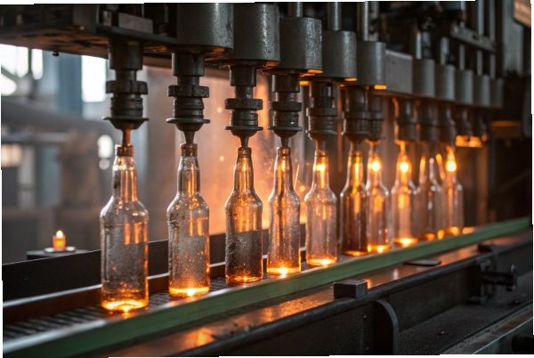
4) Cooling-rate discipline near cold surfaces
Wall crystallization is a time problem. Even if average temperature is fine, slow cooling and long hold near the wall lets nuclei grow. The goal is to reduce residence time in the danger band and avoid local “quench then hold” cycles created by unstable pull rate.
| Control knob | What it prevents | What to watch daily | Fast corrective action |
|---|---|---|---|
| Forehearth uniformity | surface crystals, devit flakes | wall temps, spout temps | rebalance burners, fix dead zones |
| Stable pull rate | cords and banding | gob temp drift, viscosity drift | stabilize batch feed and firing |
| Redox stability | Ti/Fe state drift, fining swings | O₂ in flue, batch redox index | adjust oxidizer/reducer, tighten air-fuel |
| Raw material screening | rutile/ilmenite stones | stone count, inclusion ID | tighten sand/cullet QC, sieve/clean |
| Short wall residence | wall growth of crystals | devit line frequency | adjust flow and temperature profile |
If these controls are in place, TiO₂ becomes manageable. Without them, even “low TiO₂” can still devit on the wall.
Before scaling any chemistry change, the plant needs proof tools that connect TiO₂ to liquidus and to real defects.
How can producers verify and monitor TiO₂ effects—liquidus tests, hot-stage microscopy, and on-line polariscopy—before scaling?
Scaling TiO₂ changes without proof is how plants create a long defect problem that does not show up until cullet recycles back.
The safest approach is a gated scale-up: measure liquidus by gradient furnace methods, screen crystallization with hot-stage microscopy and thermal analysis, and monitor cords/stress with optical inspection and polariscope systems while tracking stones by inclusion analytics.
1) Liquidus testing: define the real margin
Liquidus temperature is the highest temperature where melt and the first crystal can coexist in equilibrium. Standard practice uses a gradient furnace method to establish that boundary. This test gives a real “do not operate below this for long” anchor point. It also helps compare recipes objectively when TiO₂ changes.
A good bottle plant uses liquidus tests as a trend tool:
- baseline recipe at steady state
- trial recipe after cullet stabilizes
- worst-case recipe with expected cullet drift
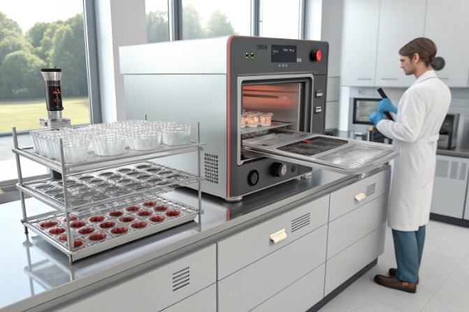
2) Hot-stage microscopy and thermal analysis: see nucleation and growth behavior
Hot-stage microscopy can screen when crystals start to appear on heating or cooling. It is not a perfect copy of a forehearth wall, but it is a fast comparator. DSC/DTA can also track Tg, crystallization peaks, and stability windows. In soda-lime silica glass studies with TiO₂ additions, thermal analysis plus microscopy and XRD were used to identify when rutile appears and how crystallization behavior shifts. That same toolset can be used as a plant screen before running full furnace trials.
3) On-line polariscopy and optical inspection: catch cords and stress early
Polariscope systems are widely used to check internal stress and annealing 8 quality in glass products. In production, stress and strain patterns also help flag unstable forming and cooling that can amplify devit and cords. On-line optical systems can be used to trend striae/cord visibility and to catch wall-crystal flakes and stones before they reach customers.
When stones appear, the plant should not guess. A basic workflow is:
- isolate defect samples
- cut and polish cross-sections
- run SEM/EDS or micro-XRF to confirm Ti-bearing inclusions vs zircon/spinel vs refractory 9 fragments
This step prevents false fixes.
| Stage | Tool | What it proves | Scale-up gate |
|---|---|---|---|
| Lab baseline | Liquidus by gradient furnace | real margin vs devit | margin must not shrink |
| Lab screening | Hot-stage + DSC/DTA + XRD | nucleation and phase ID | no new early crystallization peak |
| Pilot run | Forehearth mapping + defect trending | wall-risk behavior | devit line rate must stay flat |
| Production hold | Polariscope + optical QA + inclusion ID | cords/stress and stone origin | no Ti-bearing stone trend |
| Cullet loop check | XRF trend on cullet + batch | composition drift | TiO₂ stays within control band |
If these gates are followed, TiO₂ decisions become data decisions. That is the only safe way to scale in continuous bottle production.
Conclusion
TiO₂ can trigger devit only when the process is already close to the liquidus edge, so tight temperature uniformity, stable redox, clean raw materials, and liquidus-based proof testing matter most.
Footnotes
-
The temperature above which glass is completely liquid; falling below risks crystal growth. ↩
-
A high-temperature silica crystal that can form as a defect in glass, causing weakness. ↩
-
A measure of fluid friction; lower viscosity means glass flows more easily. ↩
-
The formation of crystals on glass surfaces, ruining clarity and strength. ↩
-
The balance of oxidation states in the melt, critical for color and stability. ↩
-
Dirty recycled glass introducing impurities that cause defects in new bottles. ↩
-
Visible lines of inhomogeneity in glass, caused by poor mixing or composition variance. ↩
-
Controlled cooling process to remove internal stress and prevent breakage. ↩
-
Heat-resistant materials lining the furnace; wear can release stone defects. ↩