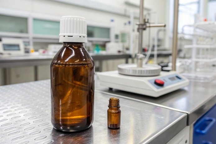
A closure can feel perfect at the capper, then leak after cooling. The usual reason is not “bad torque.” It is small movement plus big loss of gasket force.
Yes. Thread tolerance design should consider thermal expansion, because temperature changes shift thread fit and seating while liners soften and creep. Small dimensional changes can reduce engagement, increase back-off risk, and open micro-leak paths after thermal cycling.

Thermal expansion is small, but thread performance is built on small margins
Thermal expansion does not “stretch” the neck in a dramatic way. The glass finish usually changes by microns, not millimeters. Still, thread engagement and sealing are sensitive because the system is a stack of small effects that add together.
What actually changes when temperature changes
The glass neck expands a little with temperature. The cap shell (especially plastic) often expands more. The liner changes the most in behavior because it softens, creeps under load, and may not fully recover after cooling. So the thread geometry is only one piece of the sealing story, but it is the piece that controls how much clamp load reaches the liner.
Why threads can fail even when dimensions are “in spec”
Threads rarely fail because the major diameter moved by a few microns. They fail because heat changes seating, friction, and load transfer, and the thread geometry does not have enough margin for:
- finish ovality and tilt
- cap shell creep
- liner compression set
- vibration and vacuum pull during cooling
If the cap seats slightly higher due to friction changes, the liner sees less compression. If the liner relaxes, the clamp load drops. If the clamp load drops, thread friction drops. Then vibration can cause cap back-off. That chain reaction is why thread tolerances and thermal cycling belong in the same discussion.
A simple way to think about “thermal-safe” thread design
A thermal-safe closure system keeps a stable seal even after predictable torque loss. That means:
- enough thread engagement to keep retention when clamp load drops
- enough land quality so the liner can seal with lower force
- enough tolerance margin so small shifts do not cause cross-threading or tilt
| Part of the system | What heat mainly changes | Why it matters to threads | Typical field symptom |
|---|---|---|---|
| Glass finish | small expansion | slight shift in fit and seating | small drift in seating height |
| Plastic cap | larger expansion + creep | reduced retention and clamp load | torque loss, loose caps |
| Aluminum cap | moderate expansion | less creep than plastics | lower risk, still needs validation |
| Liner/gasket | softening + compression set | seal force drops over time | micro-leaks, vacuum loss |
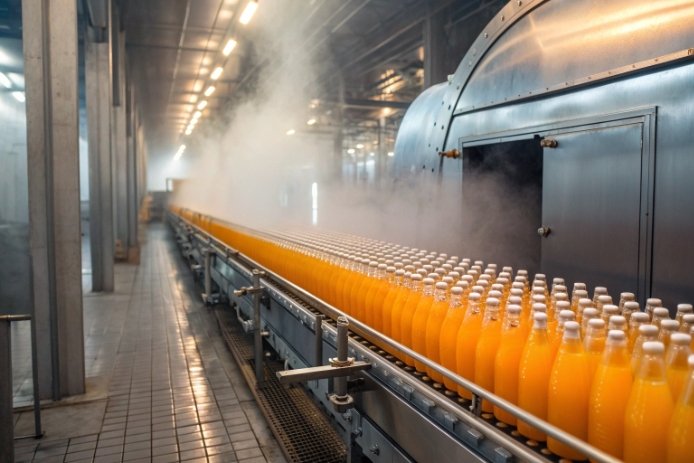
If the bottle will ever see hot-fill, pasteurization, warm warehouses, or cold-to-hot shipping, it is safer to design threads and tolerances as a heat-cycled system, not a room-temperature system.
A clean rule that works well in production is: thread tolerances should prevent mis-assembly at the coldest condition, and they should maintain retention at the hottest condition, even after liner relaxation.
Now let’s go deeper into the four practical questions.
A lot of teams start with “How much does glass move?” That is the right starting point, so we go there next.
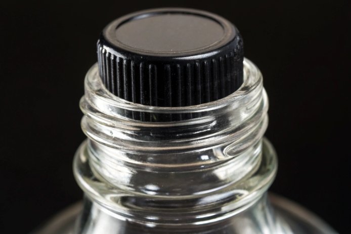
How much do glass neck finish dimensions change with temperature, and when does it affect thread engagement?
Cold bottles entering a warm capper and hot bottles cooling in a warehouse can both create complaints. Small movement can still become a big sealing problem.
Glass neck dimensions change by microns per typical process temperature swing. That change affects thread engagement when the system already has low margin from ovality, tilt, shallow engagement, or when plastic caps and liners relax under heat and reduce clamp load.
How to estimate neck diameter change
A practical estimate for diameter change is:
- ΔD = D × α × ΔT
Where:
- D is the finish diameter
- α is the glass CTE (typical soda-lime container glass is about 8–10 × 10⁻⁶ /°C)
- ΔT is the temperature change
So for a 28 mm finish and a 60°C swing:
- ΔD ≈ 28 mm × 9×10⁻⁶/°C × 60°C ≈ 0.015 mm (15 µm)
That is small. Still, it matters when the clearance between cap threads and glass threads is small, or when the cap is plastic and expands much more than glass.
When small movement becomes a real thread problem
Thread engagement becomes sensitive when any of these are true:
- Shallow engagement (few turns) so small seating shifts reduce retention
- High ovality or tilt so one side binds while the other side has clearance
- High friction scatter (wet glass, coatings, temperature drift) causing inconsistent seating height
- Plastic caps where heat reduces stiffness and the skirt can relax
- Hot-fill cycles where torque and clamp load drop before vacuum forms
The real risk is often not “the threads stop fitting.” The risk is “the cap seats differently” and the liner ends up with less compression at the weakest spot.
| Finish size example | ΔT | Estimated glass ΔD (α=9×10⁻⁶/°C) | What it can influence in practice |
|---|---|---|---|
| 28 mm | 40°C | ~10 µm | seating repeatability, tilt sensitivity |
| 28 mm | 60°C | ~15 µm | retention margin with relaxed caps |
| 38 mm | 60°C | ~21 µm | cross-thread sensitivity if ovality is high |
| 48 mm | 60°C | ~26 µm | land alignment and gasket contact ring |
The practical takeaway for design
Glass expansion alone rarely forces a redesign. It tells us the scale. The design decision is about margin:
- if engagement is deep and the land is robust, microns do not matter much
- if engagement is shallow and the liner is thin, microns plus creep can matter a lot
This is why the best approach is to design thread tolerance with a heat-cycled validation plan, not only with a room-temperature gauge plan.
Which thread parameters are most sensitive to heat (major/minor diameter, pitch, lead, and thread height)?
Some thread dimensions move with temperature, but not all dimensions create the same functional risk. The sensitive ones are the ones that change how the cap seats and how load transfers.
Major/minor diameter and effective pitch diameter are the most sensitive to heat for engagement and cross-threading risk. Thread height and lead-in geometry are the most sensitive for seating repeatability. Pitch and lead shift with temperature too, but functional problems usually come from fit, seating, and friction changes rather than pure pitch expansion.
Why diameters matter first
Diameter changes alter radial clearance. Radial clearance controls:
- how easily the cap starts without cross-threading
- how much the cap can tilt before binding
- where flank contact begins
If the cap is plastic, heat increases its diameter more than glass. That can reduce flank contact pressure and reduce retention after torque loss.
Why pitch diameter matters more than major diameter
The sealing and retention behavior depends on where the flanks touch. That is captured best by the effective pitch diameter and flank angle. A small change in how the flanks meet can change the torque-to-clamp relationship.
Why lead-in and thread height matter in real lines
Cross-threading and “false start” issues often come from:
- poor lead-in chamfer
- short or sharp start threads
- inconsistent thread height due to forming variation
Heat makes friction less stable, so weak lead-in design becomes a line defect quickly.
Heat changes the system, not only the geometry
Even if pitch and lead change slightly with temperature, the bigger effect is that:
- liners soften and reduce clamp load
- friction changes and the cap can seat higher or lower
- plastic caps creep and lose retention
So thread parameters should be evaluated with the closure material and liner behavior in mind.
| Thread parameter | Heat sensitivity (practical) | Why | What can go wrong |
|---|---|---|---|
| Major/minor diameter | High | controls clearance and tilt | cross-threading, seating scatter |
| Pitch diameter | High | governs flank contact and load transfer | torque scatter, retention loss |
| Thread height | Medium to high | affects engagement and stripping risk | shallow engagement, back-off |
| Lead/lead-in geometry | High | controls start reliability | false start, cross-thread |
| Pitch | Medium | axial step changes slowly | less common as root cause |
| Flank angle consistency | Medium to high | affects friction and clamp load | removal torque instability |
A useful design habit is to treat “thread fit” as a functional outcome. That outcome is driven by a small set of dimensions plus how the cap and liner behave at temperature.
How do hot-fill cooling cycles change application torque and removal torque for continuous thread caps?
Many teams chase torque numbers at the capper and still get leakage. That happens because the torque profile changes with time and temperature.
In hot-fill cooling cycles, application torque can be correct at capping, but clamp load drops as the liner softens and creeps. Back-off torque usually decreases during the warm hold. After cool-down, vacuum loads the seal while the liner may not fully recover, which can reduce removal torque and increase cap back-off risk.
What torque is doing in a CT system
In a continuous thread (CT) system, torque is a proxy for axial compression. The sealing force is created by:
- thread flank friction and geometry
- cap skirt stiffness
- liner compression response
Temperature changes all three. So a single torque value at time zero is not a seal guarantee.
Typical torque timeline after hot-fill
1) At capping: liner is warm, friction is high or variable, torque looks fine.
2) Warm hold: liner softens, clamp load relaxes, back-off torque drops.
3) Cool-down: vacuum forms and tests the weakest seal zone, while the liner recovery may be incomplete.
4) After 24–72 hours: compression set stabilizes, removal torque can be lower than expected, and micro-leaks may show up.
This is why “torque loss” should be expected and designed for. The target torque should produce enough residual clamp load after relaxation.
Why plastic CT caps are more sensitive
Plastic caps often:
- expand more with heat
- creep more under load
- show larger torque retention loss
Metal CT caps usually creep less, but liners still relax, so validation is still needed.
| Time point | What changes | What to measure | What failure looks like |
|---|---|---|---|
| 0–5 minutes | seating + early relaxation | application torque + immediate back-off | seating scatter |
| after heat soak | liner creep dominates | back-off torque at temperature | warm micro-leaks |
| after cool-down | vacuum pull begins | leak test + back-off torque | vacuum loss, air ingress |
| 24–72 hours | set stabilizes | removal torque + leak retest | delayed leakage, loose cap feel |
What this means for design and specs
For CT systems, a thermal-safe torque spec is not a single number. It is a range plus a retention requirement, like:
- minimum back-off torque after heat soak
- minimum back-off torque after cool-down
- leak-free performance after cycling
That approach connects torque to sealing, which is the real goal.
How can you set thread tolerances and validation tests to prevent cross-threading, cap back-off, and leakage after thermal cycling?
Thread tolerances should prevent assembly problems at the extremes and maintain retention after the system relaxes. Testing should prove that outcome, not only confirm drawings.
Set thread tolerances using functional limits that account for temperature, ovality, and seating behavior. Then validate with cold-start application trials, thermal cycling torque retention audits, and leak detection at warm and post-cool conditions. This prevents cross-threading, cap back-off, and leakage in real hot-fill distribution.

Tolerance strategy that works in production
1) Define functional engagement targets
- minimum number of engaged turns at worst case
- minimum thread flank contact stability when clamp load drops
- maximum allowable seating height variation
2) Control the real geometry drivers
Thread tolerance design should be paired with finish controls that matter most:
- roundness/ovality
- perpendicularity (tilt)
- land flatness and defect limits
These often cause more sealing issues than nominal thread diameter.
3) Design the lead-in to be forgiving
A good lead-in reduces cross-threading, especially in cold conditions and high-speed lines.
4) Set torque as a thermal-cycle requirement
Define:
- application torque range
- minimum back-off torque after heat soak
- minimum back-off torque after cool-down
- removal torque range after aging
Then link those to leak performance.
Validation tests that catch the real failure modes
A strong validation plan uses both “fit” tests and “seal” tests:
- cold-start capping trials (worst case for cross-threading)
- thermal cycling that matches your hot-fill cooling curve
- multi-time torque audits (application, hot back-off, cold back-off, 24h removal)
- vacuum/pressure decay leak tests
- dye ingress for micro-leak sensitivity
- cap back-off monitoring (witness marks or rotation checks)
| Risk to prevent | What to control in design/spec | What to test | Pass signal |
|---|---|---|---|
| Cross-threading | lead-in, clearance, ovality limits | cold-start line trial | near-zero cross-thread rate |
| Cap back-off | engagement depth, retention after creep | torque retention + vibration handling | back-off torque stays above minimum |
| Micro-leaks | land quality + liner selection | warm + post-cool leak tests | no decay, no dye ingress |
| Torque scatter | thread profile and friction stability | torque distribution study | tight Cpk / stable trend |
| Cavity-driven failures | finish geometry consistency | cavity-based sampling | no outlier cavities |
A practical habit that avoids late surprises
For every new bottle-cap combo, it helps to lock a simple release gate:
- “No cross-threading at cold start”
- “No leaks after thermal cycling”
- “Back-off torque above minimum at hot and cold time points”
That gate makes the tolerance design meaningful, because it is tied to the real outcome: stable sealing after temperature change.
Conclusion
Yes, thread tolerance should consider thermal expansion because heat changes seating, torque retention, and liner force. Functional tolerances plus thermal-cycle torque and leak validation prevent cross-threading, back-off, and leakage.