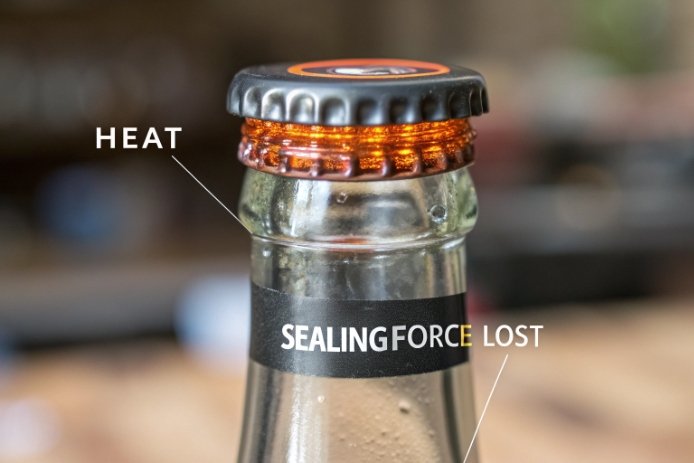
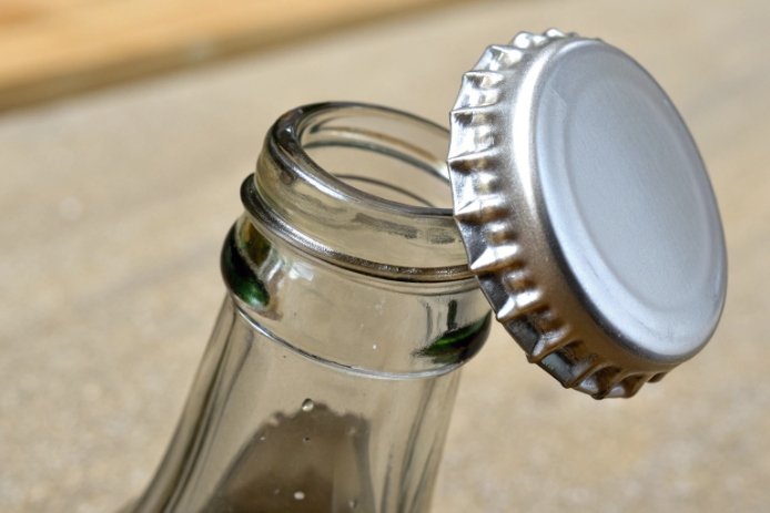
A closure can seal perfectly at 20°C and leak at 80°C. Nothing “broke.” The parts just moved by microns, and the liner lost compression at the wrong moment.
Yes. Differential thermal expansion between glass, caps, and liners changes thread fit and sealing pressure. The effect is small in size but large in sealing performance during hot-fill, pasteurization, and cooling.

Thermal expansion is not the main movement, but it triggers the main failure
For most bottle systems, glass expands modestly. Caps and liners often expand more and soften with heat. That combination changes:
-
how tight the threads sit,
-
how much torque turns into axial load,
-
how much contact pressure remains on the sealing land.
A closure system is really a spring system. The “spring” is the liner and the cap skirt. Heat can reduce that spring force by softening the liner and expanding the cap. Cooling can create vacuum and pull on the seal. If the system has low compliance or poor finish geometry, these cycles create micro-leaks.
A simple estimate helps set the scale. For soda-lime glass 1, mean linear CTE is around 8–10×10⁻⁶/K. A 28 mm finish heated by 60°C expands by about 15 µm. Aluminum and many plastics expand more. A liner also changes stiffness. Those differences can reduce compression even when diameters “look” unchanged by eye.
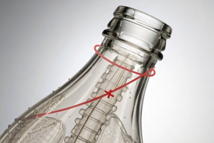
The most important point is that sealing performance depends on contact pressure and contact continuity. Tiny changes in geometry can break continuity if the finish is oval or the land is not flat. Tiny changes in load can break pressure if the liner is thin or has high compression set 2 at heat.
| Component | What changes with heat | Why it matters for sealing | What failure looks like |
|---|---|---|---|
| Glass finish | small expansion | changes seating geometry slightly | leaks at weak oval zones |
| Cap shell (Al or plastic) | larger expansion | reduces clamping/seat load | torque drops, “loose cap” feel |
| Liner | softens + relaxes | loses sealing force | short-term weeping, dye ingress |
| Product/headspace | pressure up, then vacuum | stresses seal both ways | burp leaks then suck-back |
The next sections answer your four questions in detail: how differential expansion changes sealing, which closures are most heat-sensitive, what happens during hot-fill and cooling, and how to design tolerances and liner choices to prevent leakage after thermal cycling.
How does differential thermal expansion between glass, aluminum/plastic caps, and liner materials change sealing performance?
Thermal expansion changes fit. Liner softening changes force. Together they decide whether the seal stays tight.
Differential expansion changes sealing by altering thread engagement and the axial load that compresses the liner. Caps (especially plastics) expand more than glass, while liners soften and creep at heat, reducing compression and creating leak paths during pressure and vacuum transitions.
Glass vs aluminum vs plastic: why the cap often “moves more”
-
Glass has modest expansion.
-
Aluminum expands more than glass.
-
Many plastics expand much more than glass.
When the cap expands more than the finish, the cap’s internal diameter and skirt can open slightly. That can reduce how firmly the threads hold, especially in systems where the cap relies on hoop tension for retention.
Liner behavior matters as much as expansion
Most liners are polymer-based. At hot-fill 3 temperatures, they:
-
soften,
-
lose modulus (spring force),
-
creep under load (compression set),
-
then recover only partly after cooling.
Even if the geometry returns after cooling, the liner may not return fully. That can reduce long-term seal force.
Why the same system can leak only during a short window
Short-term leakage often happens when:
-
the liner is warm and soft,
-
internal pressure is highest right after fill,
-
the finish has local low-contact zones due to ovality.
Later, as temperatures equalize and pressure drops, the leak can stop. But the damage is done: sticky necks, label failures, corrosion, and microbial risk.
| Mechanism | Expansion/softening effect | Seal impact | Typical time window |
|---|---|---|---|
| Cap expands more than glass | thread fit relaxes | less load transfer | during heat soak |
| Liner softens/creeps | seal force drops | micro-channels open | minutes to hours |
| Pressure rise in headspace | pushes on seal | demands higher load | right after fill |
| Vacuum on cooling | pulls on seal | tests micro-leaks | during cool-down |
A closure system that seals well through cycles is designed to keep adequate compression even after some torque loss and liner relaxation.
Which closure systems are most sensitive to heat (ROPP, lug/twist-off, continuous thread, pump/sprayer), and why?
Different closures tolerate movement differently. Heat sensitivity depends on how the system creates sealing force and how much compliance it has.
Heat-sensitive systems are usually those with thin sealing lands, low compliance, or strong dependence on torque retention. ROPP and lug closures can be sensitive to finish variation and liner behavior. Plastic continuous-thread systems can be sensitive because plastic expands and creeps more. Pumps/sprayers add more parts and leak paths, so thermal cycling can expose weakness faster.
ROPP (roll-on pilfer proof)
ROPP forms threads into aluminum during capping. This can be stable, but it is sensitive to:
-
finish OD and roundness (because the cap is formed to the glass),
-
land flatness (seal quality),
-
liner choice (compression and recovery).
Heat can reduce clamp load and soften liners. If the finish has ovality, the formed cap may not maintain uniform load around the circumference under cycling.
Lug / Twist-off (TO)
Lug systems often depend on specific cam engagement and liner compression. They can be sensitive to:
-
finish geometry (lug finish dimensions),
-
application temperature,
-
vacuum formation after cooling (common in food jars).
If torque is low or liner relaxation is high, vacuum can pull air in during cooling, causing loss of vacuum and leaks.
Continuous thread (CT)
CT can be very robust, but sensitivity depends on cap material:
-
Metal CT: often stable, good torque retention.
-
Plastic CT: more expansion and creep, so heat cycling can reduce torque and seal force more quickly.
Pumps and sprayers
These are often the most complex. They include:
-
a closure shell,
-
a liner or gasket,
-
a dip tube fit,
-
extra leak paths at interfaces.
Heat can change gasket compression and part geometry, and vibration during transport can worsen marginal seals after a thermal cycle.
| Closure type | Why heat sensitivity happens | Biggest weak point | Best stabilization lever |
|---|---|---|---|
| ROPP 4 | formed skirt load changes with heat | roundness + land | finish control + liner choice |
| Lug/TO | relies on compression + vacuum | sealing surface + vacuum | liner for vacuum + capper control |
| CT (plastic) | creep and expansion reduce load | torque retention | material + torque spec + land width |
| Pump/sprayer | multiple interfaces | gasket + pump fit | gasket design + leak testing |
Heat sensitivity is not a verdict on the closure type. It is a reminder to design the finish, liner, and application conditions as one system.
What happens to torque, thread engagement, and sealing surface compression during hot-fill, pasteurization, and cooling?
A closure system changes in three phases: heat-in, hold, and cool-down. Each phase stresses a different part of the seal.
During heating, caps and liners expand and soften, often reducing torque retention and seal compression. During hot-fill and pasteurization, internal pressure can rise and push against the seal. During cooling, vacuum can pull on the seal and reveal micro-leaks, especially if the liner has relaxed or the finish is oval.
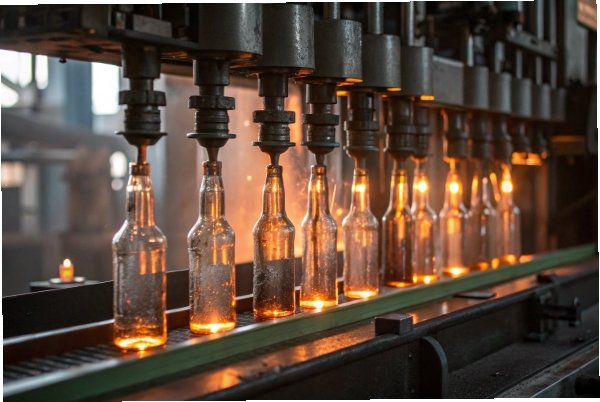
Phase 1: Hot-fill / heat-up
-
Glass finish expands slightly.
-
Cap expands more (especially plastic), which can loosen thread grip.
-
Liner softens and can creep.
-
Product and headspace pressure rise.
Net result: seal needs to maintain compression under higher pressure with materials that are losing stiffness. This is when short-term weeping happens.
Phase 2: Hold / dwell (pasteurization or warm hold)
-
Liner creep continues under sustained compression.
-
Torque can relax (back-off torque drops).
-
Any uneven finish geometry becomes more important.
Net result: the seal force can drop even without visible changes.
Phase 3: Cooling
-
Cap and liner cool and shrink.
-
Vacuum may form inside the bottle.
-
If the liner does not recover, seal force can remain lower than the starting value.
-
Micro-leaks allow air ingress, loss of vacuum, or sticky residue.
Net result: leaks can appear during cooling or later in storage.
| Thermal cycle stage | Mechanical change | Sealing risk | What to measure |
|---|---|---|---|
| Heat-in (hot-fill) | load loss + pressure rise | weeping | hot leak test + torque at heat |
| Warm hold | creep/relaxation | torque drop | back-off torque trend |
| Cool-down | vacuum + recovery limits | suck-back or loss of vacuum | vacuum retention + dye ingress |
| Storage | compression set continues | delayed leakage | aged torque + leak test |
The best systems keep enough liner compression even after predictable torque loss. That is why finish tolerances and liner selection must be designed together.
How can you design neck finish tolerances and choose liner materials to prevent leakage after thermal cycling?
Many projects try to solve leakage by raising torque. That can cause finish cracks and does not fix geometry or liner behavior. A better solution is a tolerance and liner plan that keeps seal force stable.
Prevent leakage after thermal cycling by controlling finish roundness and land flatness, avoiding sharp thickness transitions at the finish, and choosing liners with low compression set and stable sealing over the target temperature range. Validate with hot-cycle torque retention and leak testing using worst-case bottles and caps.
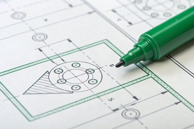
Finish tolerance priorities that matter most at temperature
1) Ovality/roundness: local gaps create weak seal zones.
2) Top land flatness and width: controls contact continuity and compression margin.
3) Finish perpendicularity: tilt creates uneven compression around the circle.
4) Thread profile consistency: ensures predictable seating and load transfer.
5) Surface quality: chips, checks, or scuffs become leak paths when liners soften.
A practical tolerance strategy includes both minimum and maximum limits, and it is enforced by cavity-level measurement. A single cavity drift can create most of the field leaks.
Liner selection rules for thermal cycling
Liner choice is usually the most powerful lever for leak resistance at heat:
-
Choose liners designed for hot-fill or retort 5 where needed.
-
Favor materials with low compression set at the relevant temperature.
-
Match liner hardness to land geometry (too soft can creep; too hard can fail on minor waviness).
-
For vacuum systems (lug/TO), choose liners that maintain seal under vacuum and recover after cycles.
Typical liner families vary by market, but the selection logic stays the same: stable compression, low creep at temperature, and good recovery after cooling.
Design the seal with a “compression margin”
A robust system has enough compression margin that a small loss of force (from expansion or creep) still leaves a positive sealing pressure. That requires:
-
adequate land width and smoothness,
-
enough liner thickness,
-
torque targets with a safe band,
-
and a finish OD/height that seats predictably.
| Control lever | What it protects | How to specify it | How to verify it |
|---|---|---|---|
| Finish ovality | contact continuity | max roundness limit | ring gauge + roundness check |
| Land flatness | sealing ring integrity | flatness spec + visual standard | optical inspection + gauges |
| Thread geometry | seating repeatability | profile tolerance | CMM 6 or profile gauge |
| Liner compression set | long-term seal force | liner grade for heat range | aging + torque retention |
| Torque window | seal load without cracking | min/max torque | capper study + audits |
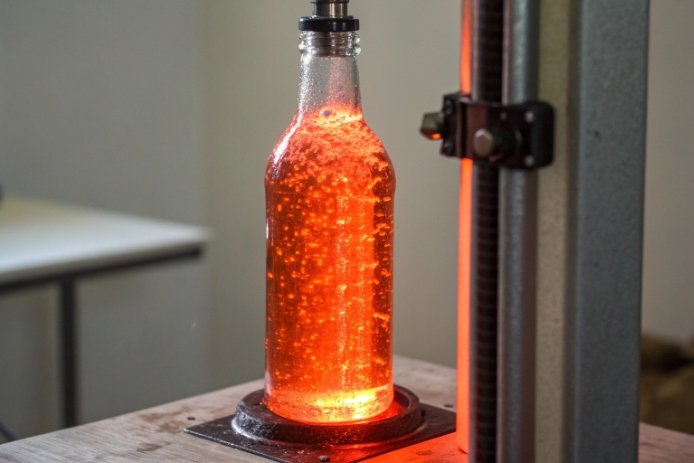
The validation plan that prevents surprise leaks
-
Run hot-fill or pasteurization simulation with real timing.
-
Measure application torque and back-off torque immediately, after heat soak, after cool-down, and after 24–72 hours.
-
Run leak tests at heat and after cooling (vacuum/pressure decay + dye ingress for sensitivity).
-
Sample across cavities and include worst-case finish ovality bottles.
When these steps are in place, thermal expansion stops being a risk multiplier. It becomes a predictable input that the closure system is designed to tolerate.
Conclusion
Thermal expansion affects closure fit through small dimensional shifts and large liner force changes. Control finish geometry, select heat-stable liners, and validate with hot-cycle torque and leak tests to prevent leakage.
-
Basic composition and properties of standard container glass. ↩
-
Permanent deformation of a material remaining after compression. ↩
-
Filling process requiring thermal stability from bottle and cap. ↩
-
Standard neck finish type often used with aluminum caps. ↩
-
Process using heat and pressure to sterilize food products. ↩
-
High-precision instrument for measuring complex 3D geometries. ↩