A closure can pass leak tests at room temperature and still fail on a hot-fill line. The bottle did not “change size” in a dramatic way. The neck just moved a few microns, and that was enough to break a seal.
Yes. The neck finish diameter expands when heated, and you can estimate the change using CTE and the temperature rise. The size change is small, but it can affect liner compression, thread engagement, and leak risk during hot-fill or thermal cycling.

How heat-driven neck expansion turns into real closure performance
Thermal expansion 1 is predictable. Seal performance is not always predictable, because the closure system has several materials that respond differently to heat. Glass expands a little. Metals expand more. Plastics expand a lot more. Liners soften and relax. Product inside the bottle warms and can increase pressure. All those effects stack in the finish area, which is already the most geometry-sensitive zone on the container.
What “diameter changes” means for a neck finish
A typical neck finish 2 dimension change from heating is measured in micrometers (µm), not millimeters. Yet seals operate on contact pressure and small gaps. A change of 10–30 µm can matter if:
-
the liner compression margin is small,
-
the finish is slightly oval,
-
the top sealing land is narrow,
-
the closure torque is near the low limit,
-
the product pressure rises during heating.
The one formula that keeps teams aligned
For a first estimate, treat the finish as a simple ring:
ΔD = D₀ × α × ΔT
-
ΔD = change in diameter
-
D₀ = original diameter
-
α = mean linear CTE of the bottle glass (per °C or per K)
-
ΔT = temperature rise (°C or K)
This estimate is good enough to compare designs and to size tolerance budgets. For final validation, the bottle needs real capping trials and leak testing at temperature.
| Item | What it controls | Why it matters at temperature | Typical failure symptom |
|---|---|---|---|
| Glass CTE | how much the finish grows | sets baseline movement | small but consistent drift |
| Cap material CTE | differential movement | changes thread fit and load | torque drop at heat |
| Liner behavior | compression and recovery | seal pressure changes with heat | weeping, dye ingress |
| Finish ovality | local gaps | amplifies tiny expansion effects | leaks only from some cavities |
| Internal pressure | load on seal | pushes liner away from land | “burp” leaks during hot-fill |
Now the practical questions: how much diameter really changes with temperature, whether leakage can happen during heating, which neck dimensions are most sensitive, and how to test closure integrity before shipment.
If this feels like a small detail, that is exactly why it causes expensive returns. It is easy to ignore until a line runs hot.
How much does neck diameter expand with temperature, and how can you estimate it from CTE and the temperature rise?
Small heating changes can create big packaging arguments. The fastest way to stop the debate is to calculate the size change in microns and compare it to your tolerance and liner compression window.
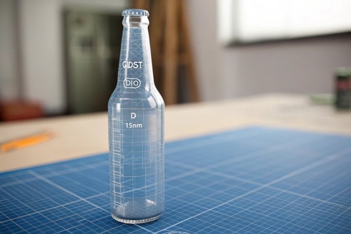
Estimate neck expansion with ΔD = D₀ × α × ΔT. For a 28.0 mm finish, α = 9.0×10⁻⁶/K, and ΔT = 60°C, the diameter grows by about 0.015 mm (15 µm).

A worked example that matches bottle reality
Assume:
-
Finish outside diameter D₀ = 28.00 mm
-
Soda-lime container glass 3 mean CTE α = 9.0 × 10⁻⁶ /°C
-
Heating from 20°C to 80°C → ΔT = 60°C
Then:
-
ΔD = 28.00 mm × 9.0×10⁻⁶/°C × 60°C
-
ΔD = 28.00 × 540×10⁻⁶ mm
-
ΔD = 0.01512 mm ≈ 15 µm
That number looks tiny. Yet 15 µm is meaningful if your liner compression margin is thin or if the finish is oval by 0.10–0.20 mm and the closure is already sealing at the edge of the land.
What this estimate does not include
The formula above is purely geometric. It does not include:
-
temperature gradients through the finish thickness,
-
localized heating (hot product touching the bore first),
-
mechanical loads from torque and threads,
-
time-dependent liner relaxation at heat.
In real hot-fill, the inner finish can warm faster than the outer finish. This creates temporary thermal stress 4 and can create slightly different local expansion. That is why the same bottle may leak during the first minute and then stop leaking once temperatures equalize.
How to use the estimate in design reviews
The best use is to compare “movement” to “tolerance budget”:
-
If your finish OD tolerance is ±0.20 mm, the thermal expansion of ~0.015 mm is not the main dimension swing.
-
If your liner compression margin is only 0.05–0.10 mm, the thermal expansion can become a real contributor.
| Input | Typical value | Effect on ΔD | Why it matters |
|---|---|---|---|
| Finish OD (D₀) | 28–48 mm | larger OD → larger ΔD | wide-mouth moves more |
| Glass CTE (α) | 8–10×10⁻⁶/K | higher α → larger ΔD | recipe changes can shift α |
| Temperature rise (ΔT) | 30–90°C | higher ΔT → larger ΔD | hot-fill and retort are harsher |
| Ovality | 0.05–0.25 mm | amplifies local gaps | drives “random” leaks |
| Liner set | time + heat dependent | reduces seal load | the main reason torque drops |
A clear estimate gives the team a shared baseline. Then the right next step is to look at differential expansion with the cap and liner, because that is where leakage risk typically appears.
Can heating cause short-term closure leakage due to differential expansion between glass and cap liners?
A closure can feel tight at room temperature, then start weeping during hot-fill. Many teams blame “bad torque.” Often the real driver is differential expansion plus liner softening.
Yes. Heating can cause short-term leakage because the cap and liner usually expand and relax more than the glass finish. This can reduce liner compression and change thread load, especially during fast heating, pressure rise, or stop-start cooling events.
Why the cap system changes more than the glass
Glass expansion is modest. Cap systems often move more:
-
Aluminum caps expand more than glass.
-
Plastic caps expand much more than glass.
-
Liners soften at heat and can lose compression force over time (compression set 5).
Even if the glass finish expands outward, the cap may expand even more. That can reduce contact pressure in certain thread and liner geometries. At the same time, hot product can increase internal pressure, which pushes against the seal interface.
The two leakage moments that show up in hot processes
1) Right after fill (heat + pressure spike):
The product heats the bore and top land first. Pressure rises. The liner is warm and soft. A small gap or low contact pressure becomes a leak path.
2) During cooling (vacuum + relaxation):
As the product cools, vacuum forms. If the liner has relaxed and the cap has “settled,” outside air can be pulled in, or product can weep through micro-channels during pressure swings.
What makes leakage “short-term” instead of permanent
Many leaks appear only in a time window because:
-
temperatures equalize through the finish,
-
liners re-seat as pressure changes,
-
the cap and glass return toward room temperature.
Still, short-term leaks can cause serious secondary problems: sticky necks, label failures, corrosion, microbial risk, and customer complaints.
| Driver | What changes at heat | How it affects sealing | Common field symptom |
|---|---|---|---|
| Cap expands faster than glass | thread fit loosens | lower load transfer | low back-off torque |
| Liner softens | contact pressure drops | micro-channels open | weeping at the land |
| Product pressure rises | pushes from inside | seal load must be higher | “burp” leaks after fill |
| Finish ovality | uneven contact ring | local weak points | leaks only from some cavities |
| Over-lubrication | slip at threads/land | torque retention drops | random seal failures |
The most reliable way to prevent short-term leakage is to design the finish and liner as a system, then validate at temperature with real process timing. That starts with knowing which neck dimensions are most heat-sensitive.
Which neck finish dimensions are most sensitive to heat (outer diameter, thread profile, sealing surface), and how do you control tolerances?
When heat causes leakage, the failure point is rarely “the whole neck.” It is usually one critical contact surface or one thread feature that loses load when the system warms.
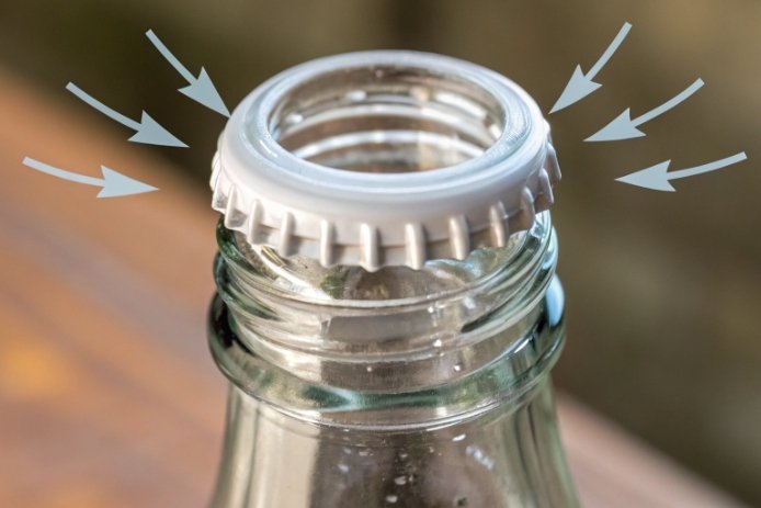
The most heat-sensitive features are the top sealing surface (land), finish ovality, and thread geometry that controls liner compression and cap retention. Control comes from tight finish tolerances, stable forming/annealing, and cavity-level measurement of OD, land flatness, and thread profile.
1) The sealing surface is the real hero
Most closures seal on the top land or a defined sealing ring. Heat matters because:
-
the liner must keep enough compression against the land,
-
small waviness or chips become leak paths when the liner softens,
-
any tilt at the finish changes compression around the circumference.
If the land width is too narrow, contact pressure concentrates and becomes sensitive to small ovality. If it is too wide but not flat, micro-gaps remain.
2) Finish OD and ovality drive thread engagement and contact ring consistency
Outer diameter growth with temperature is small, but ovality and tolerance stack-ups are not small. A finish that is 0.15 mm oval can create a local low-pressure zone. Heat then reduces liner stiffness and makes that weak point leak first.
3) Thread profile controls load transfer under torque retention loss
Thread height, pitch, and lead-in affect:
-
how the cap seats,
-
how much torque becomes axial compression on the liner,
-
how resistant the system is to torque relaxation.
At heat, torque retention usually drops because liners relax and cap materials expand. A thread system that still maintains axial load after some torque loss is more forgiving.
How to control tolerances without making the bottle expensive
The main control is process stability, not “tighter drawings” alone:
-
stabilize gob temperature and weight to reduce ovality,
-
keep finish tooling in good condition to avoid asymmetry,
-
control lehr profile 6 to reduce residual stress distortion,
-
measure by cavity and stop drift early.
| Feature | Why it is sensitive at heat | Practical tolerance control | Best measurement tool |
|---|---|---|---|
| Top land flatness | liner softens and needs full contact | tooling + handling + inspection | optical flatness / gauges |
| Finish OD | affects cap fit and seating | forming stability | ring gauges / CMM |
| Ovality | creates local low seal pressure | cavity tuning | roundness measurement |
| Thread height/profile | controls load transfer | mold maintenance | profile gauges / CMM |
| Finish perpendicularity | tilts seal ring | lehr handling and takeout | vision + mechanical gauges |
The goal is not perfection. The goal is a finish that remains within the seal’s compression window even when the system warms and relaxes. The last step is to prove that with heating-cycle tests that match the customer line.
What tests simulate heating cycles to verify closure fit and seal integrity (hot-fill trials, torque tests, leak tests)?
Lab numbers help, but they do not replace a real closure test at temperature. The best programs test the worst-case bottle, the worst-case cap, and the worst-case timing.
Use hot-fill or retort simulation trials with controlled temperature ramps, then measure torque retention and run leak tests at heat and after cooling. Pair this with stress inspection and finish dimension sampling by cavity to catch the true weak spots.
1) Hot-fill simulation that matches the real line
A useful hot-fill trial includes:
-
preconditioning bottles to a defined starting temperature,
-
filling to target temperature,
-
holding for a defined time,
-
applying closure at the intended capping temperature and time,
-
running the real cooling steps (including any rinse),
-
adding stop-start scenarios if the line experiences them.
This is where short-term leakage shows up. Many systems leak only in the first 1–5 minutes.
2) Torque and back-off torque tests as the “health meter”
Torque is not the seal. Still, torque retention correlates with seal load in many systems.
Key torque checks:
-
application torque at capping,
-
immediate back-off torque,
-
back-off torque after heat soak,
-
back-off torque after full cool-down,
-
torque after 24–72 hours storage (liner set).
A good program records torque by cavity and by cap lot because variability can hide in either place.
3) Leak testing that covers pressure and vacuum behaviors
Leak tests should match your product risk:
-
pressure leak tests for carbonated or warm-filled products,
-
vacuum decay tests 7 for vacuum-sealed systems,
-
dye ingress tests for micro-channels,
-
bubble tests (water bath) for quick screening.
For harsh programs, add thermal cycling: repeated heat/cool cycles can reveal liner fatigue and finish weaknesses.
| Test | What it proves | When to run it | Pass/fail example |
|---|---|---|---|
| Hot-fill simulation | real ΔT and timing risk | every new design and change | zero leaks under defined cycle |
| Retort/sterilization replication | harsh cycling performance | for sterilized products | no cracks, no seal failures |
| Torque retention | axial load stability | each batch or weekly | within torque band after heat |
| Vacuum/pressure leak test | seal integrity | per lot sampling | no decay beyond limit |
| Dye ingress | micro-leak sensitivity | qualification and audits | no dye penetration |
| Finish stress inspection | residual stress risk | per shift | stress pattern within limit |
Sampling standards that stop “average passes, worst fails”
To avoid shipping a weak cavity:
-
sample across cavities (or rotate to full coverage daily),
-
sample heavy-base and high-ovality extremes,
-
sample after any lehr, mold, or cap-lot change,
-
keep retention samples for traceability.
A closure seal is only as good as the worst cavity at the worst time window. Testing must be built around that truth.
Conclusion
Uneven heating can change neck dimensions by microns, and that can still break a seal. Tight finish control, good annealing, and real hot-cycle seal tests prevent leaks before shipment.
-
The rate at which materials change size with temperature. ↩
-
Standardized threading and sealing geometry for bottles. ↩
-
Common glass composition used for mass-produced containers. ↩
-
Internal forces caused by temperature gradients in glass. ↩
-
Permanent deformation of a material after compression. ↩
-
Annealing oven temperature profile crucial for stress relief. ↩
-
Non-destructive method for testing package seal integrity. ↩