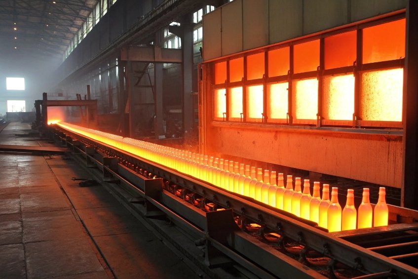
Thermal shock is the invisible enemy of a glass bottle. One fast temperature jump is enough to turn a perfect container into sharp fragments on the line or in a customer’s hand.
Thermal shock performance is the maximum temperature difference (ΔT) that a glass bottle can survive without cracking during a rapid temperature change, usually measured in standardized hot–cold water bath tests.

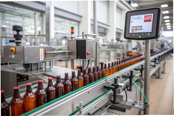
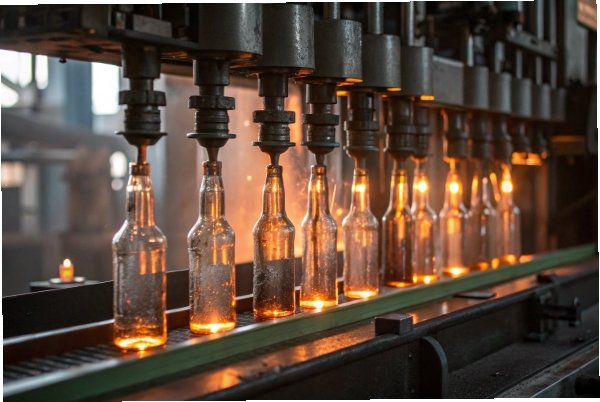
Thermal shock sounds abstract, but it is very practical. It tells us if a container will live through hot-fill, tunnel pasteurization, dishwashing, or a consumer pouring hot liquid into a cool bottle. When this value is clear, line design and bottle design become much safer.
How is allowable ΔT defined and measured in lab tests?
A bottle does not fail because the fill is hot. It fails because one side heats faster than the other. Lab tests try to copy this risk in a controlled way.
Allowable ΔT is the maximum hot–cold temperature difference a bottle survives in a standardized test, while “thermal shock endurance” is the ΔT at which a defined share of bottles, often 50%, fail.
How standard tests define ΔT
Thermal shock tests look simple from outside. Bottles go into water, bottles come out, some break. The details matter a lot though.
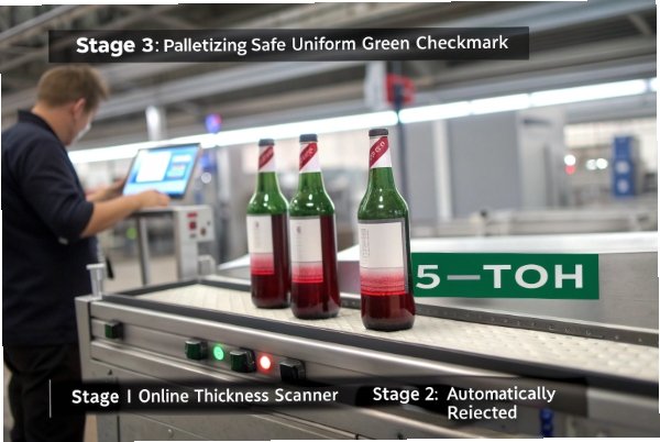
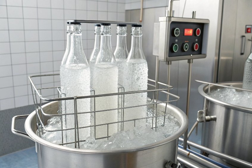
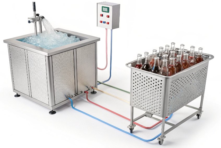
In most methods, bottles stand upright in a basket. A test cycle includes two baths. One is hot water. One is cold water. The lab sets a defined hot temperature and a defined cold temperature. The difference between them is the ΔT. The basket holds the bottles for a fixed time in the first bath. Then it moves them quickly into the second bath. The bottles stay there for a set time. The lab records which bottles break and where they break.
There are two key outputs:
- Thermal shock resistance: the highest ΔT where all bottles survive.
- Thermal shock endurance: the ΔT where a target share of bottles fail. Often this is 50%.
Standards like the ISO 7459:2004 thermal shock test methods for glass containers 1 or the ASTM C149 thermal shock resistance test method 2 describe basket design, fill level, water circulation, and transfer time. This keeps results comparable between labs. Test ΔT steps usually increase in fixed increments. The lab may test, for example, 30 °C, 40 °C, 50 °C, 60 °C, and so on, until the breakage pattern reaches the defined endurance point.
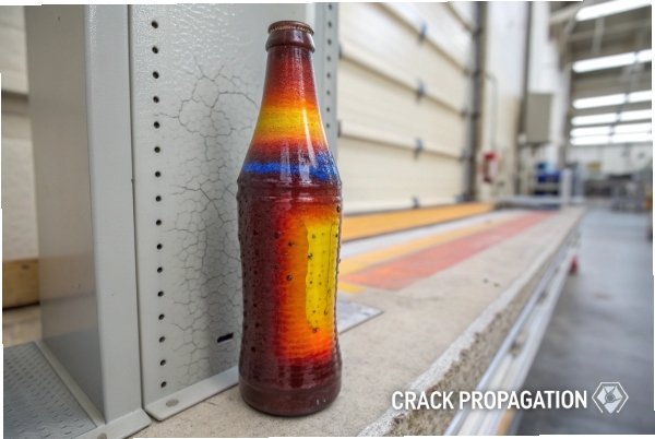
In daily work, the most useful part is not only the “big number” for ΔT. The failure pattern also tells a story. If most cracks start at the heel or shoulder, design and forming are part of the problem. If random wall breaks appear, annealing or handling may be weaker.
A simple summary of the main test concepts looks like this:
| Term | Simple meaning | How it is used in projects |
|---|---|---|
| ΔT (Delta T) | Hot bath minus cold bath temperature | Main measure of shock severity |
| Thermal shock resistance | Highest ΔT with 0% break | Design and QA acceptance target |
| Thermal shock endurance | ΔT where 50% (or set %) break | Long-term robustness comparison |
| Failure location mapping | Where cracks start on bottle | Guides design and process improvements |
So every “ΔT rating” for a bottle comes from this kind of hot–cold test. It is not a guess. It is a measured boundary for safe operation.
Which factors—annealing quality, wall thickness, geometry—drive results?
Two bottles from the same glass batch can show very different shock results. The reason is not only chemistry. It is also how the bottle was formed, cooled, handled, and shaped.
Thermal shock performance depends strongly on residual stress from annealing, local wall thickness and thickness variation, bottle geometry, surface flaws, and the base glass CTE. All these factors stack together.
The main drivers behind thermal shock strength
When a bottle hits a hot bath or hot fill, the inner and outer surfaces move to different temperatures at different speeds. The glass wants to expand or contract. It cannot do that freely, so internal stress grows. If local tensile stress passes the strength of the glass at a surface flaw, a crack starts.
Several practical factors decide how soon this happens.
1. Annealing quality in the lehr
The annealing lehr relieves internal stress after forming. If this step is weak, hidden stress stays inside the bottle. This stress adds to any new stress from a hot–cold shock. So poorly annealed glass can fail at much lower ΔT, even if wall thickness and shape are the same.
Typical signs of poor annealing include:
- Strong color patterns under a polariscope.
- Repeatable break patterns at the same height.
- Sensitive behavior to small ΔT changes in lab tests.
(For plants that want a consistent way to grade anneal condition, the ASTM C148 polariscopic examination methods for glass containers 3 are a common reference.)
2. Wall thickness and its variation
Thicker glass has more temperature gradient through the wall. The inner surface heats faster than the outer surface. The thicker the wall, the higher the stress for the same ΔT. Uneven thickness is even worse. A thick “lump” near the heel or shoulder builds higher local stress than a uniform panel.
So thermal shock is not only about “thin or thick,” but about “how even” the thickness is. Good forming and process control create more uniform walls and better performance.
3. Geometry and transitions
Geometry changes concentrate stress. The heel radius, shoulder angle, neck transitions, and base push-up all affect how heat flows and how stress distributes. Sharp angles or sudden section changes act like stress amplifiers. Smooth radii and gradual transitions spread stress more evenly.
4. Surface flaws and handling
Scratches, scuffs, and tiny stones or blisters in the wall act as crack starters. Under thermal stress, cracks often begin at these flaws. Cold-end coating, good conveyor design, and careful bulk handling help keep surfaces smoother and stronger.
This table brings the main factors together:
| Factor | Direction that helps ΔT performance | Why it helps |
|---|---|---|
| Annealing quality | Lower residual stress | Less stress added to thermal shock load |
| Wall thickness | Thinner, more uniform | Smaller gradients, lower peak stress |
| Geometry | Smooth radii, gentle transitions | Less stress concentration |
| Surface condition | Fewer scratches, better coatings | Higher effective strength at surface |
| Glass composition | Lower CTE, better homogeneity | Less expansion mismatch during temperature jump |
In day-to-day terms, the “same” bottle drawing can have very different thermal shock results when any of these factors change on the line.
Do coatings and surface treatments improve or reduce thermal shock strength?
Many people think of coatings only as a way to make bottles look nice or slip better on conveyors. But these thin layers also change how the surface handles stress.
Hot-end and cold-end coatings usually improve thermal shock performance, because they protect the surface from scratches and preserve the natural strength of the glass. Some heavy decorations or rough coatings can reduce performance if they damage or weaken the surface.
How coatings interact with thermal shock
Glass is strongest in theory when its surface is perfectly smooth and flaw-free. In the real world, bottles rub in bulk crates, slide on metal guides, and hit each other on conveyors. Each contact can cut the surface strength with tiny cracks.
Hot-end and cold-end coatings act like armor against these small injuries.
1. Hot-end coating
This is often a tin oxide or similar layer, applied at high temperature just after forming. It forms a very thin, hard layer that improves adhesion of later cold-end coatings. On its own, it does not “add strength” like tempering. Its main value for thermal shock is indirect. It helps later coatings stick well and keeps the surface more stable.
2. Cold-end coating
Cold-end coatings are usually polyethylene or other waxy materials sprayed at lower temperature. They reduce friction bottle-to-bottle and bottle-to-metal. So they reduce scratching during transport and filling. Fewer scratches mean fewer crack starters under thermal stress.
(If you want a technical overview of why hot-end and cold-end treatments work as a pair, see these container-glass surface treatments lecture notes 4.)
In practice, a bottle with a good coating system and gentle handling will keep much more of its original strength. That means a higher effective ΔT in the same lab test.
3. Decorative and special coatings
Printed ceramic inks, organic paints, metallization, frosting, and etching change the surface in different ways:
- Some paint systems are soft and do not cut the glass, so they do little harm.
- Deep acid etching or heavy sandblasting can remove material and create stress risers.
- Local heating during decoration firing can also introduce new residual stress if not well controlled.
So decoration can both help and hurt. It helps when it spreads stress and protects surfaces. It hurts when it creates rough spots, stress concentration, or extra defects.
A simple way to view coating impact is:
| Coating / treatment type | Typical impact on thermal shock | Notes |
|---|---|---|
| Hot-end + cold-end line coating | Improves | Protects from handling damage |
| Light organic decoration | Neutral to slightly positive | Depends on process and cure |
| Deep etching / heavy sandblast | Often reduces | Introduces surface flaws |
| Metallization with hard edges | Can reduce locally | Edge chips and sharp transitions can crack |
So coatings are not magic, but when they are done well, they are strong allies for thermal shock performance.
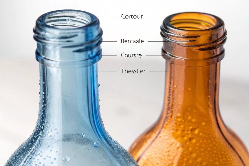
What design choices mitigate crack initiation at heel and shoulder zones?
In almost every thermal shock failure review, broken bottles tell the same story. Cracks often start near the heel or at the shoulder. These are not random spots. They are where geometry and thickness change.
To reduce crack initiation at heel and shoulder, bottle design should use generous radii, smooth transitions, controlled wall and base thickness, stable push-up design, and good support ring and finish design, all paired with solid annealing and handling control.
Designing safer heels and shoulders
The heel is the curved transition from sidewall to base. The shoulder is the curved transition from sidewall to neck. Both areas see strong temperature gradients and strong mechanical loads.
Several design rules help here.
1. Use generous radii and smooth curves
Sharp corners focus stress. So heel and shoulder should have smooth, generous radii. A round heel spreads thermal and mechanical loads around the bottle. A smooth shoulder reduces both forming stress and later thermal stress.
2. Control thickness and avoid lumps
Many forming problems push extra glass into the heel or shoulder. These local thick spots act like small heat sinks. They heat and cool more slowly than the rest of the wall. So they hold higher stress during a fast temperature jump. Better gob control, mold design, and time-pressure settings help keep thickness more uniform in these zones.
3. Base and push-up design
A deep, narrow push-up can be a weak spot in thermal and mechanical terms. A more open, smooth push-up with even thickness and good radius transitions spreads stress better. The contact ring where the bottle stands should also avoid sharp steps.
4. Finish and support ring
During hot-fill and capping, the top of the bottle sees strong loads through the support ring and finish. If the neck design sends too much stress into the shoulder area, cracks can start there under combined thermal and mechanical load. A well-balanced finish and ring design reduces this risk.
(For a clear, practical explanation of thermal shock behavior and why low-CTE glasses tolerate larger ΔT, this American Ceramic Society thermal shock lesson 5 is a useful reference. For deeper modeling and parameter-based comparisons, see this open-access study on thermal shock resistance parameters 6.)
The key design tools for these zones look like this:
| Design choice | Heel / shoulder effect | Benefit for thermal shock |
|---|---|---|
| Larger radii | Lower local stress | Fewer crack starts in hot spots |
| Uniform wall thickness | Smaller gradients | More even heating and cooling |
| Smooth push-up transitions | Less base stress | Lower break rate at base and heel |
| Balanced neck and finish | Better load path | Less shoulder cracking during hot-fill |
| Good mold and gob control | Better repeatability | Narrower ΔT performance spread |
When design, forming, annealing, coating, and handling all work together, the heel and shoulder stop being the first failure point. They become strong, quiet parts of the bottle that survive both the lab test and the real world.
(If your quality system also needs a broader “brittle materials” thermal shock reference beyond containers, the BS EN 1183 thermal shock and endurance test methods 7 are often cited in lab service catalogs.)
Conclusion
Thermal shock performance is not a single magic number. It is the result of glass type, design, annealing, coatings, and handling working together to control stress during every fast temperature change.
Footnotes
-
Official ISO listing for the container thermal shock test method referenced in specifications. ↩ ↩
-
ASTM reference page for the common thermal shock resistance method used by bottle plants. ↩ ↩
-
Standard method for checking container anneal condition via polariscopic retardation patterns. ↩ ↩
-
Technical overview of hot-end/cold-end glass surface treatments and why they reduce damage. ↩ ↩
-
Clear primer on thermal shock concepts and why CTE strongly affects allowable ΔT. ↩ ↩
-
Open-access paper explaining thermal shock resistance parameters and how they relate to cracking. ↩ ↩
-
Broad lab standard for thermal shock/endurance testing of brittle materials often referenced by test houses. ↩ ↩